In the majority of the lightning claims that I have had that were actually lightning, there were burned wires and flash burn marks to the frame.
For Maximum Resolution, Click on the Body of the Picture.
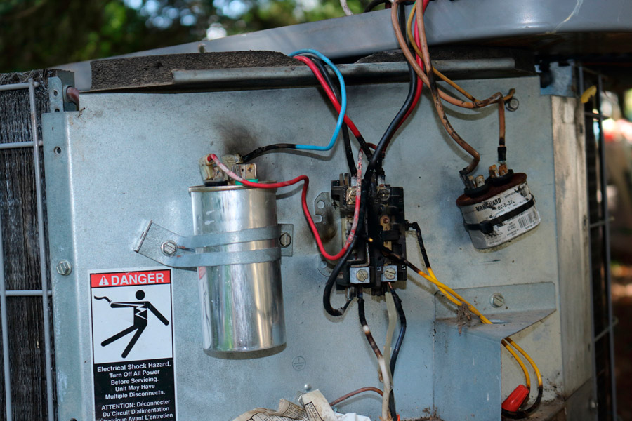
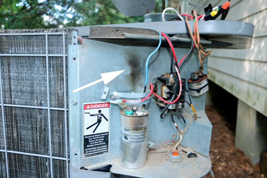
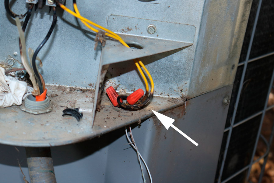
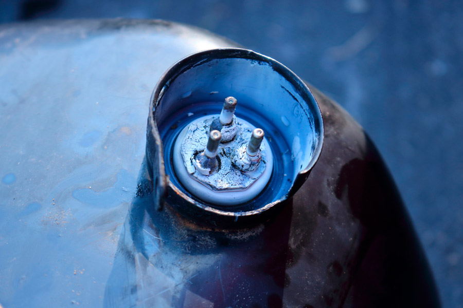
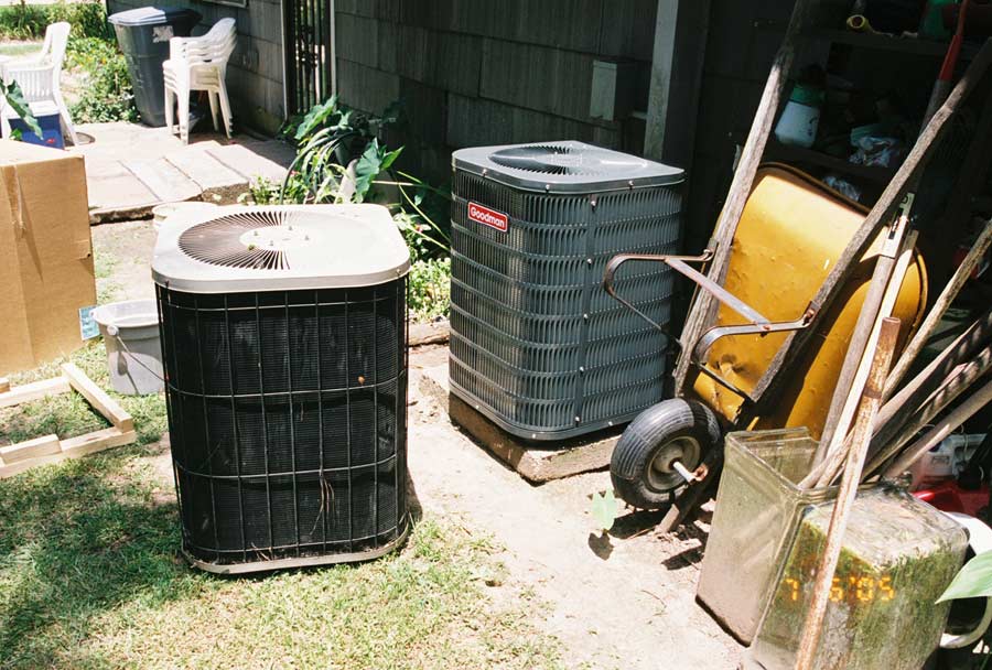
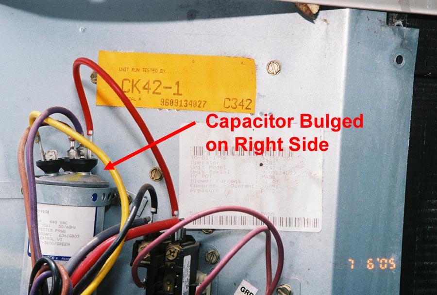
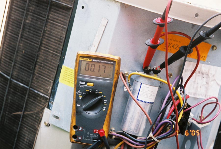
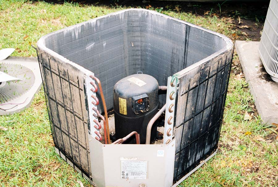
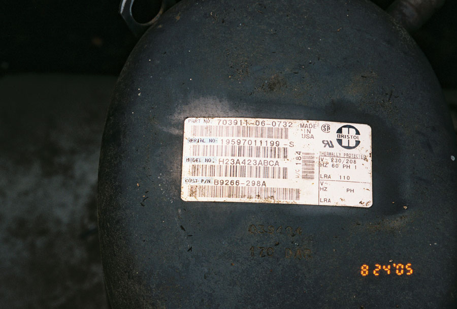
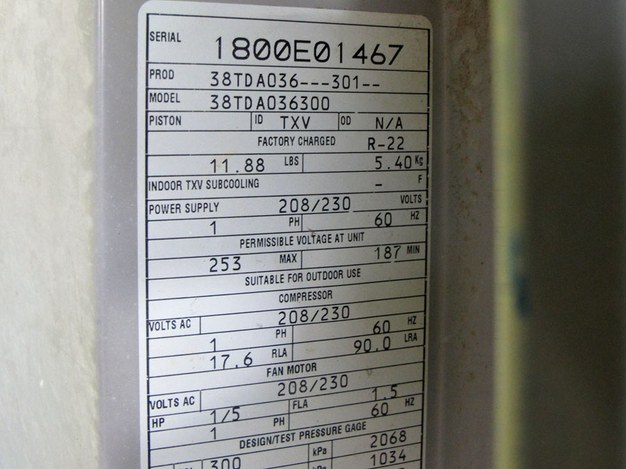
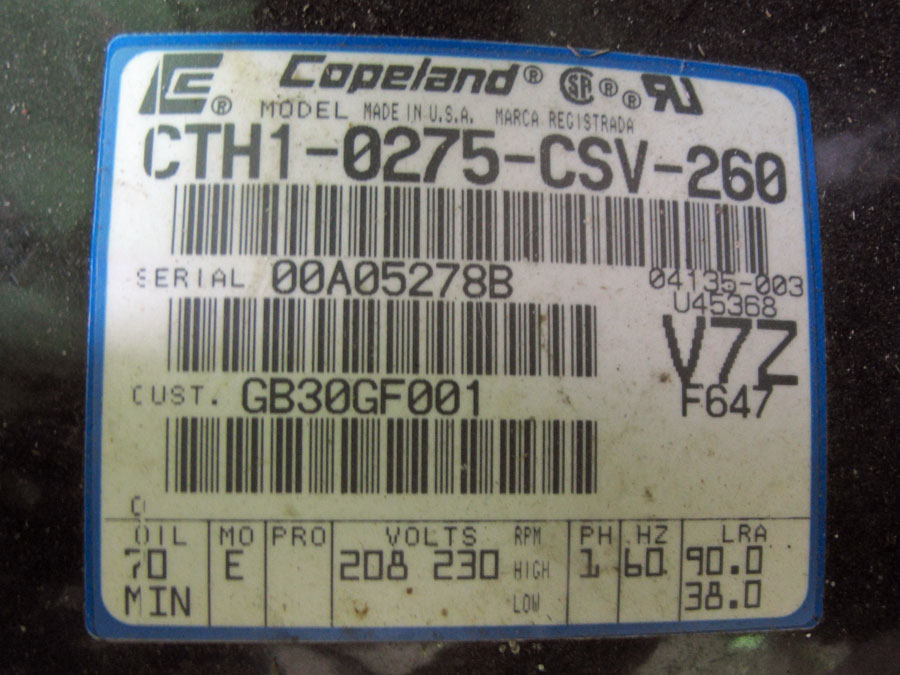
Case History: This case exemplifies why insurance companies check for lightning damage. This four-year old central air conditioning unit was replaced with a new one at cost of $1,600 to the insured. The air condition technician said that he believed that it was lightning damage because both the fan and the compressor went out at the same time. When the insurance adjuster asked the technician about the compressor, he said that it was shorted to ground, and when he attempted to start the unit, it just hummed. The adjuster also questioned the technician about the capacitor, and he stated, he checked it. The insurance adjuster was smart enough to know that if the compressor had been shorted then when the technician attempted to start the unit, the circuit breaker should have tripped. The capacitor is actually two capacitors in one metallic can; one for the compressor and one for the fan. As depicted in the photographs, the capacitor was bulged, and it was the culprit. Furthermore, you cannot check the winding of the compressor to see if they are shorted to ground without first removing the bad capacitor. After replacing the capacitor, the unit ran flawlessly.
For Maximum Resolution, Click on the Body of the Picture.
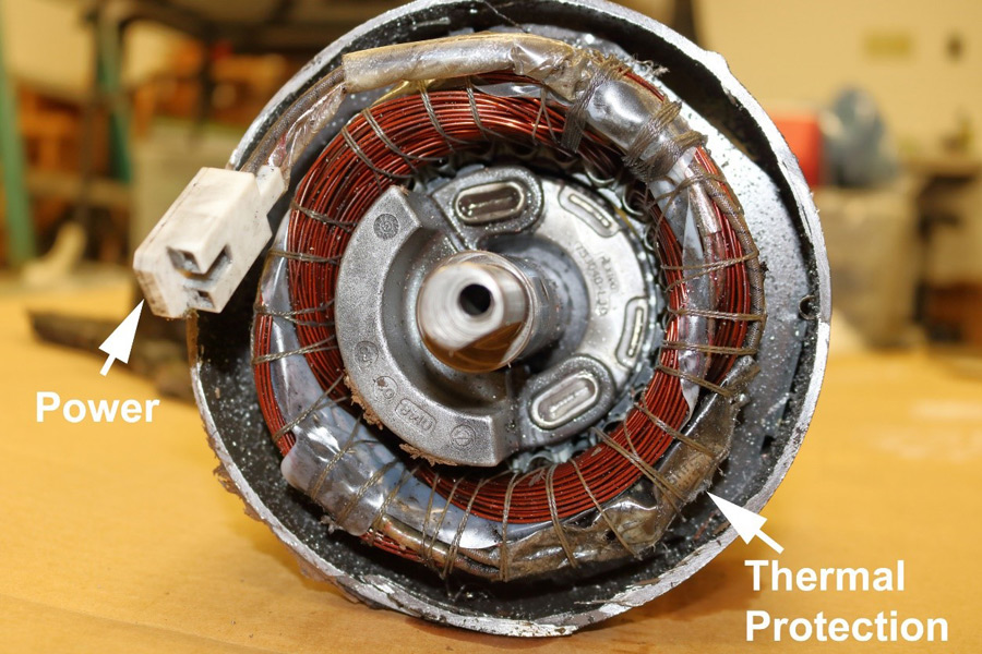
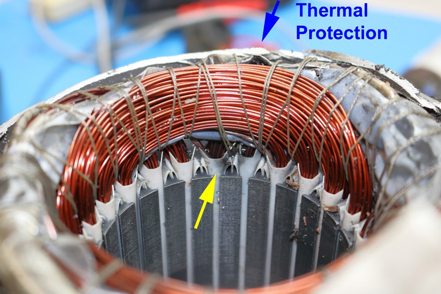
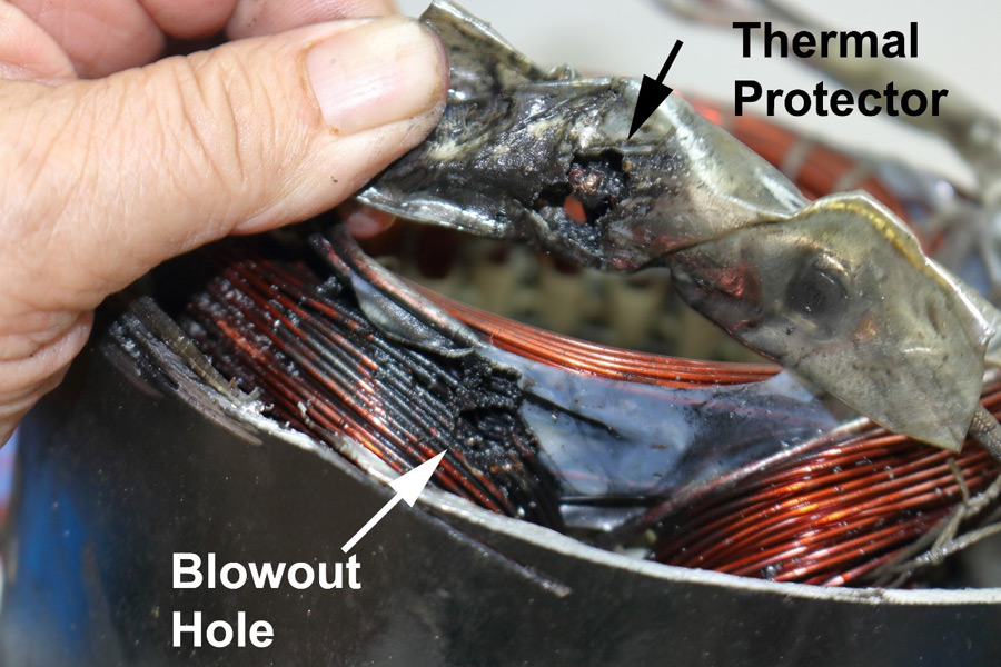
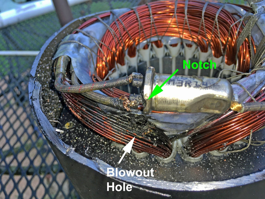
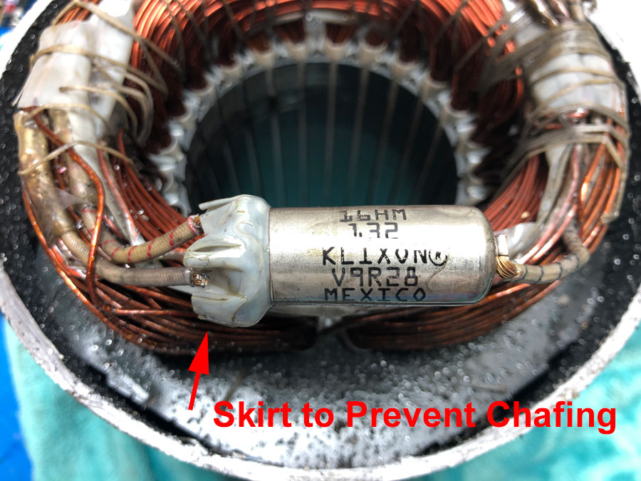
This compressor failured because the thermal protector in compressor motor had a lip on it that rubbed against the motor winding (Case No. F17-047). To prevent this, some thermal protectors have a plastic or mylar skirt that goes over the lip (see the section below on "Thermal Protection".
For Maximum Resolution, Click on the Body of the Picture.
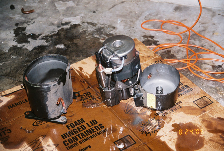
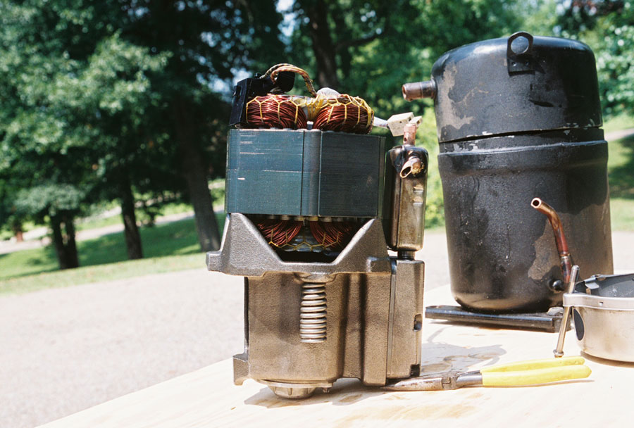
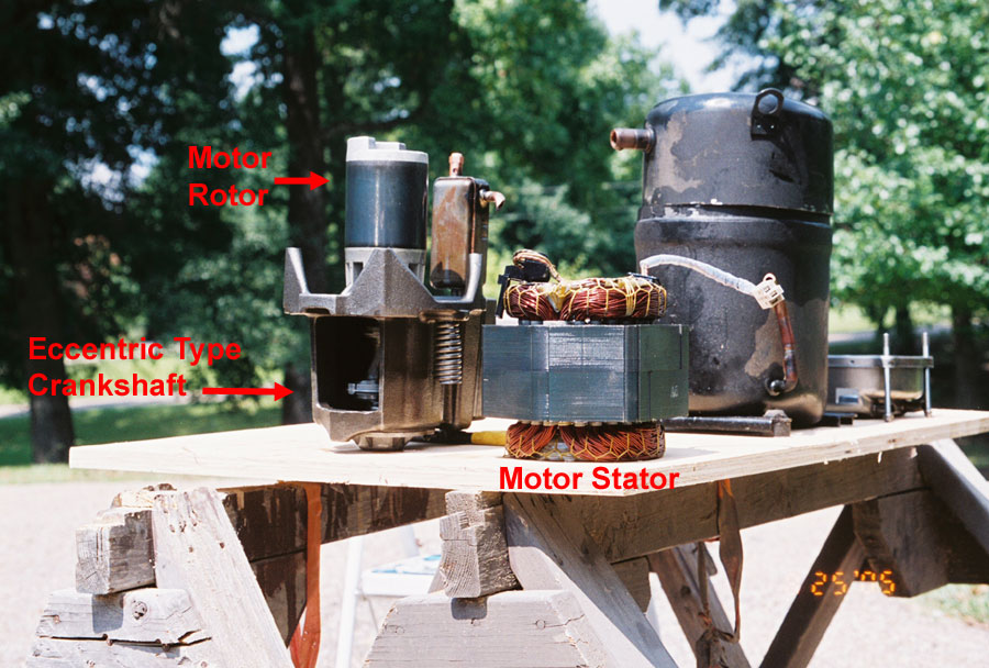
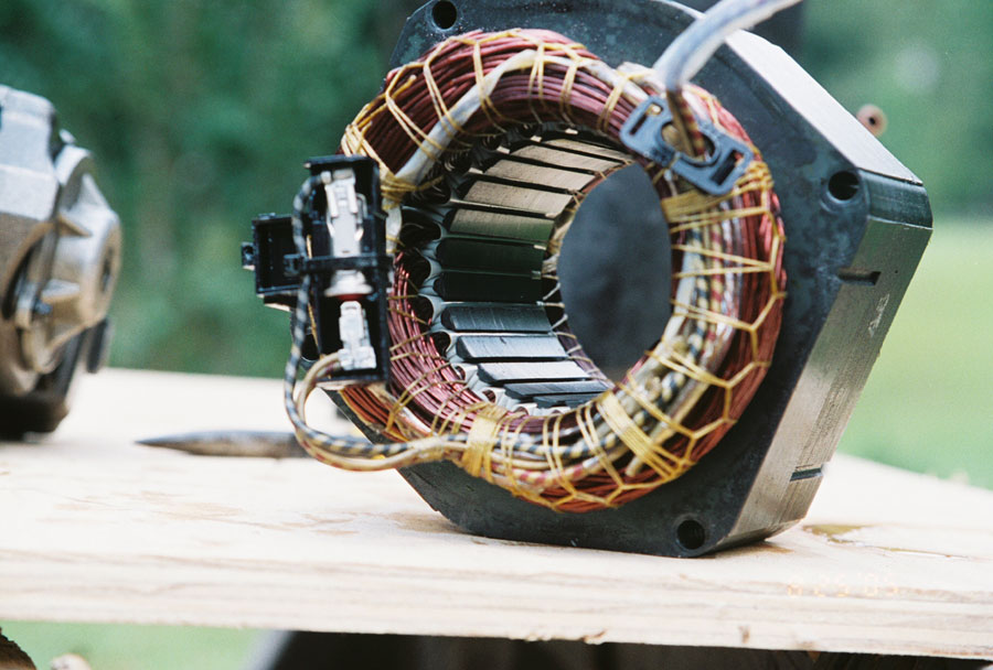
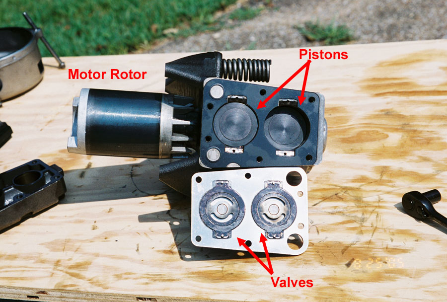
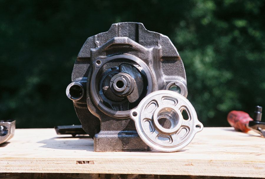
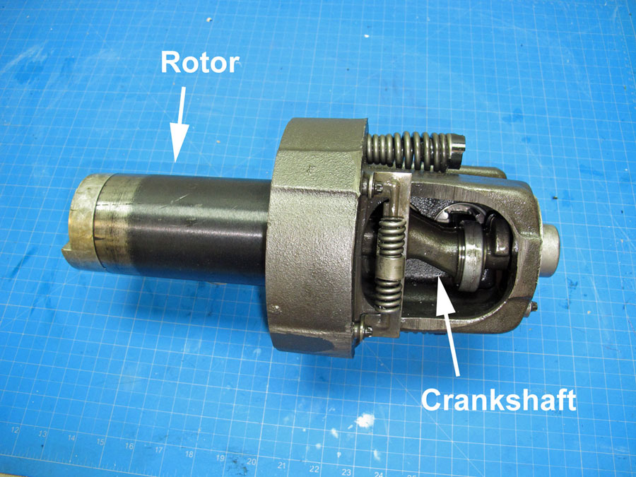
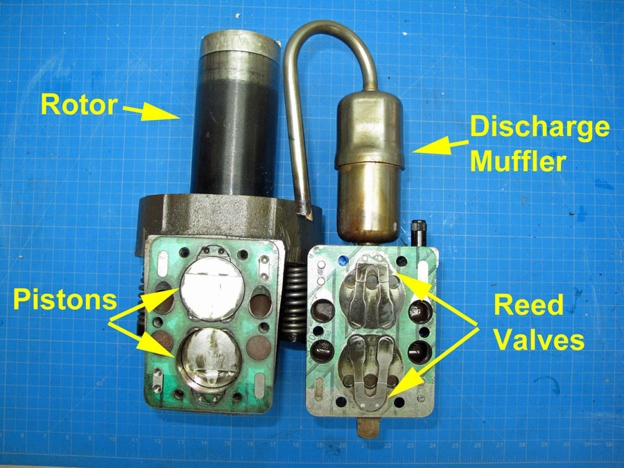
Reciprocating Compressor consist of a electric motor that drives a crankshaft piston.
For Maximum Resolution, Click on the Body of the Picture.
| Carrier - Single Phase Compressors C=Common, R=Run, S=Start |
|
| Winding | Resistance |
| C-R | 0.6 |
| C-S | 5.2 |
| S-R | 5.8 |
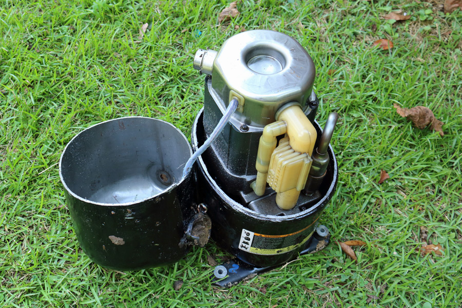
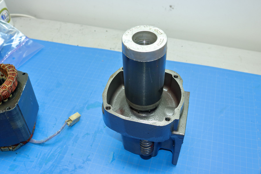
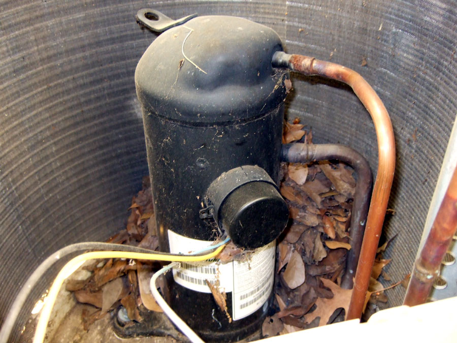
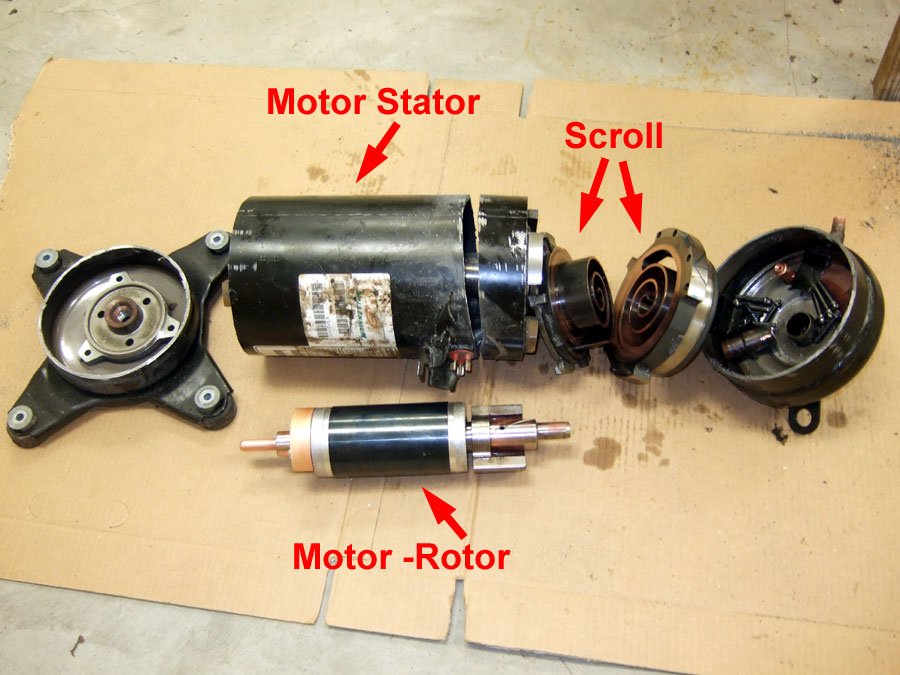
Scroll compressors pump refrigerant by the interaction of a stationary and orbiting scroll.
There are no suction or discharge valves. Scroll compressors have less moving parts,
and they are more tolerant of liquid slugging and flooded starts. To view the all of the internal parts,
the containment vessel has to be cut three times.
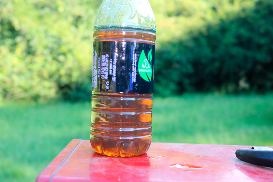
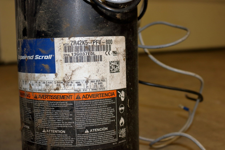
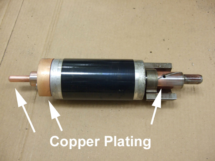
This scroll compressor failed due to moisture getting into to the system.
Most refrigerant contain chlorine, which will slowly mix with water to from hydrochloric acids.
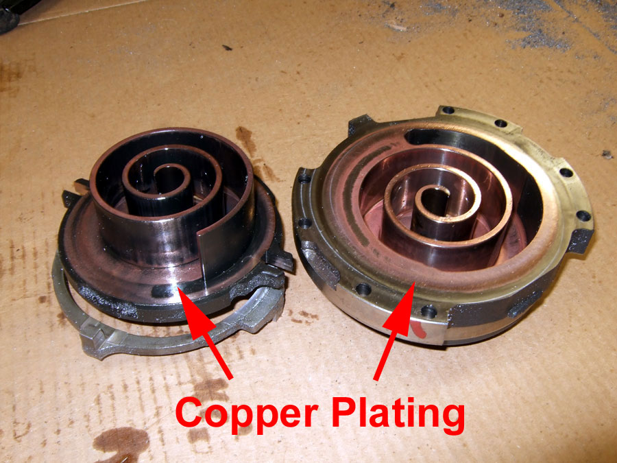
The hydrochloric acids dissolve or leach copper from the refrigeration lines and coils,
and the copper is deposited or plated onto non-copper components. In this case,
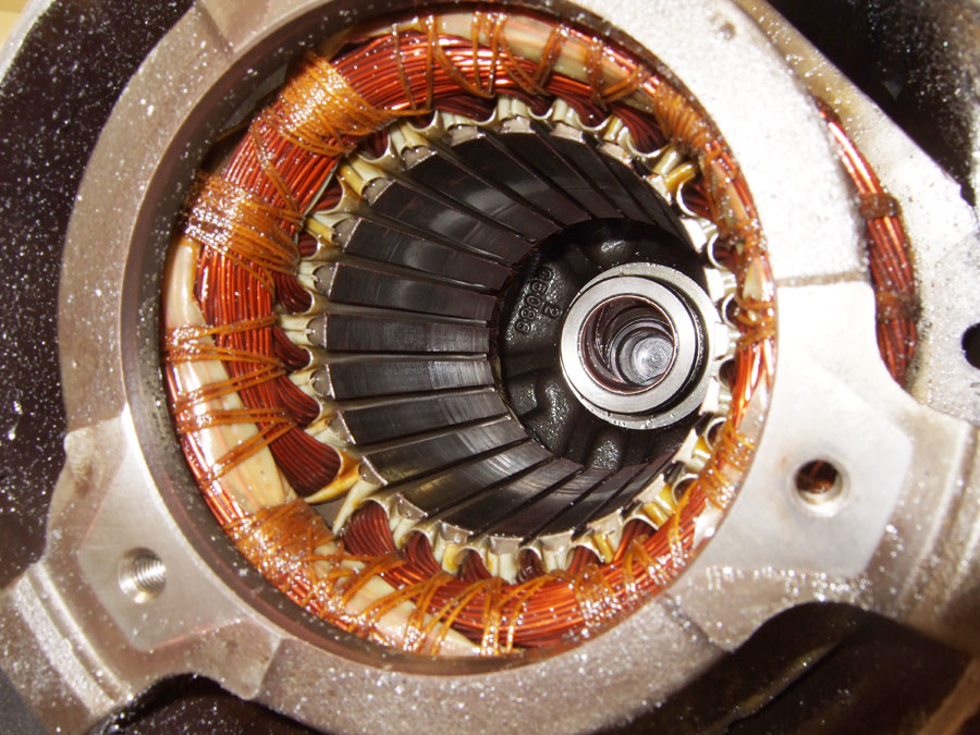
the failure was due to hydrochloric acids dissolving the enamel insulation on the motor wire.
It is not known when or how moister entered the refrigeration system, but the compressor was
manufactured in 1997, and it did not fail until 2007.
For Maximum Resolution, Click on the Body of the Picture.
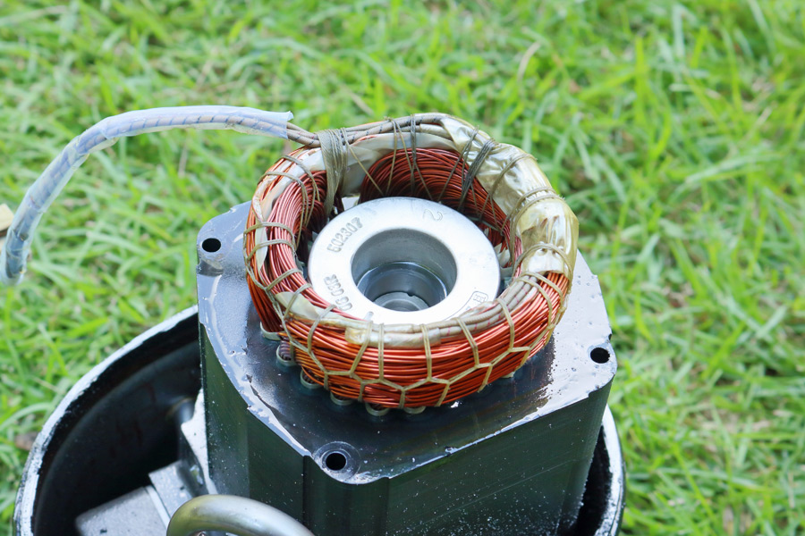
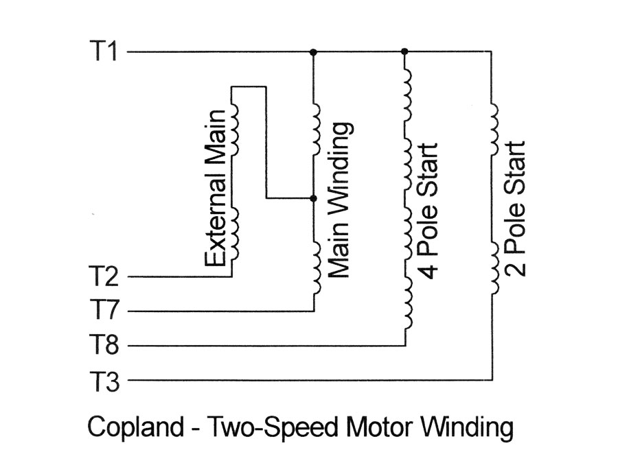
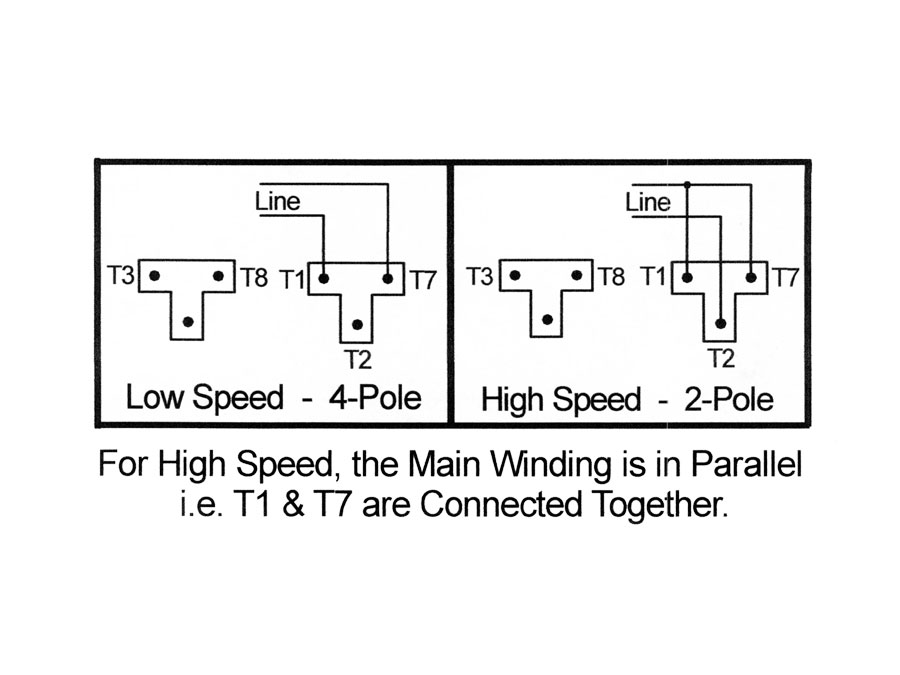
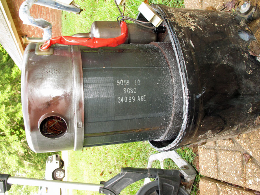
Two speed compressors change speed to match the load requirement. Doubling the speed of the motor nearly doubles the capacity (tonnage) of the system. The speed of the motor is changed by connecting the motor windings in series or parallel to form either a 4-pole (1750 rpm) or 2-pole (3500 rpm) motor.
For Maximum Resolution, Click on the Body of the Picture.
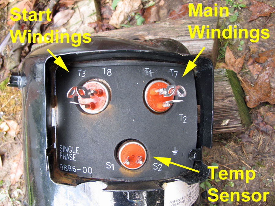
| Carrier - Two-Speed Compressor Winding Resistance at 70°F |
||||
| Winding | 3 TON | 4 TON | 5 TON | |
| T1-T2 | Ext. Main | 0.80 | 0.70 | 0.60 |
| T1-T3 | 2-Pole Start | 3.20 | 2.20 | 1.80 |
| T1-T7 | Main | 1.30 | 1.00 | 1.00 |
| T1-T8 | 4-Pole Start | 3.10 | 2.20 | 2.00 |
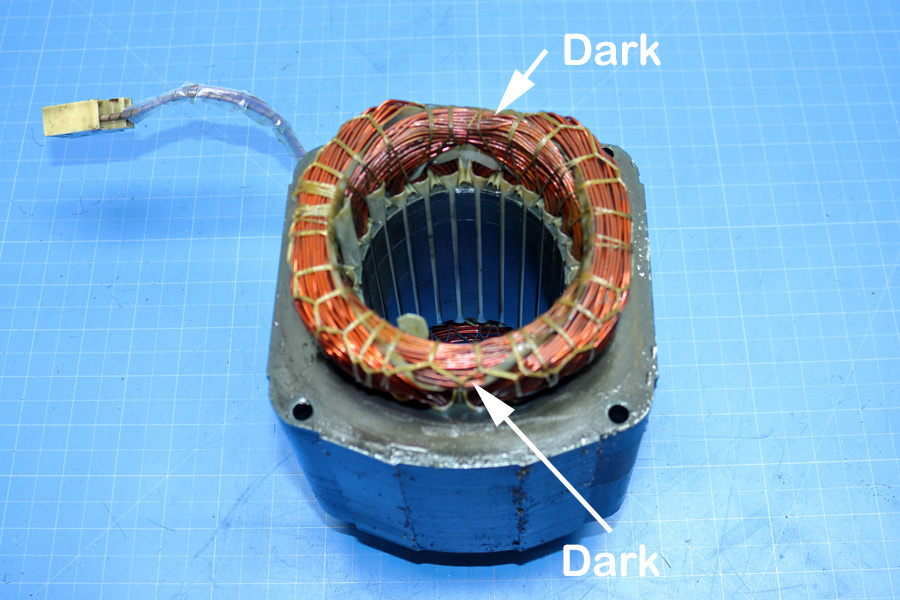
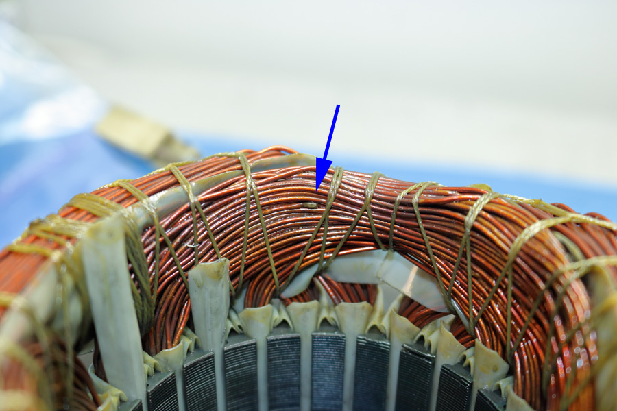
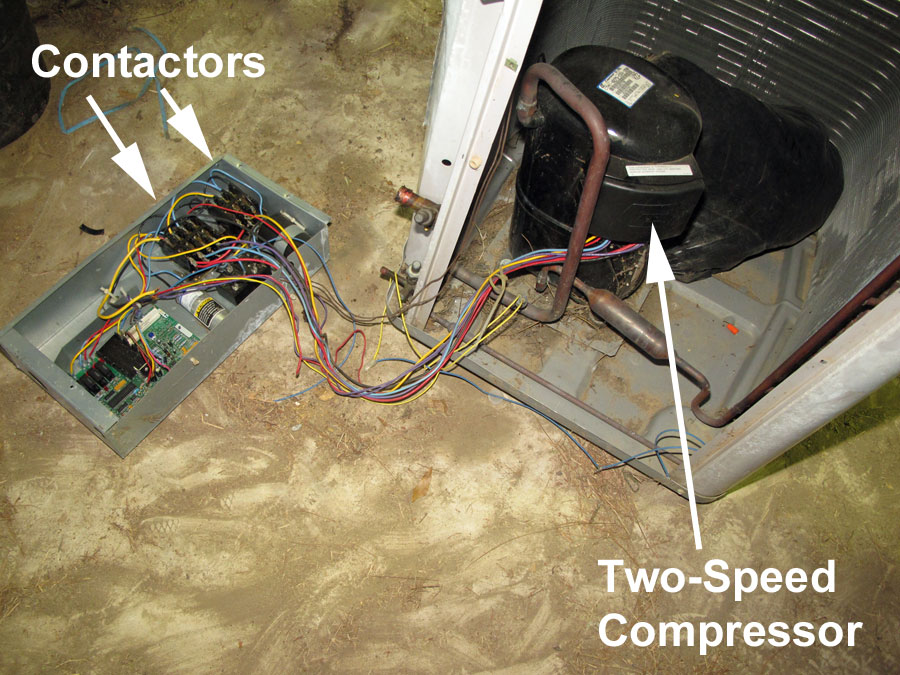
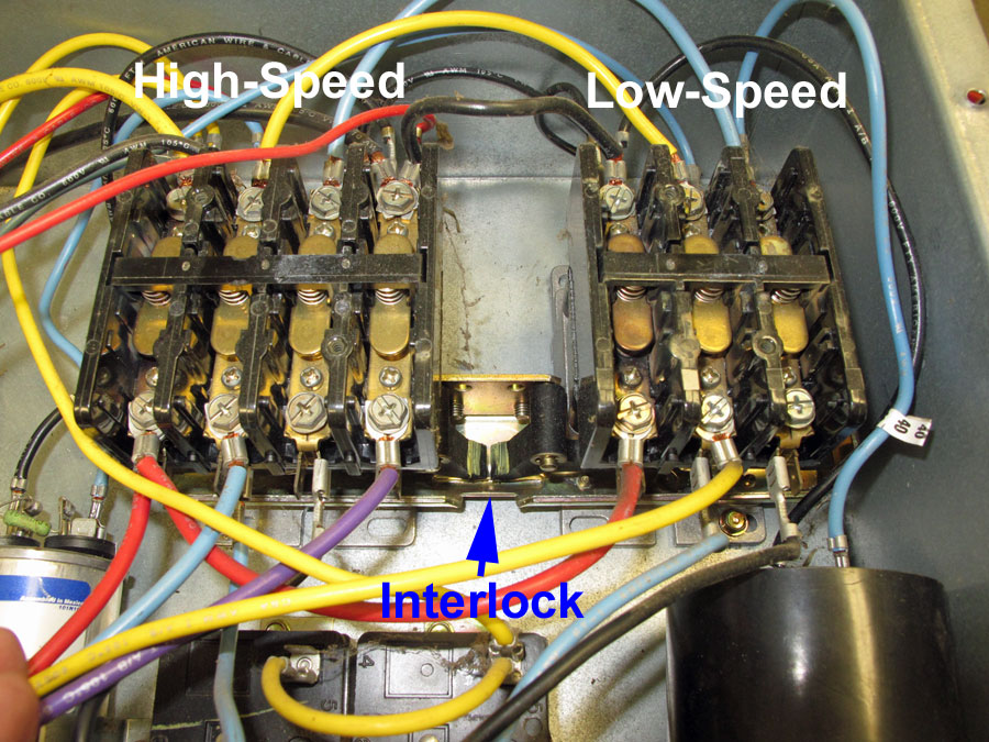
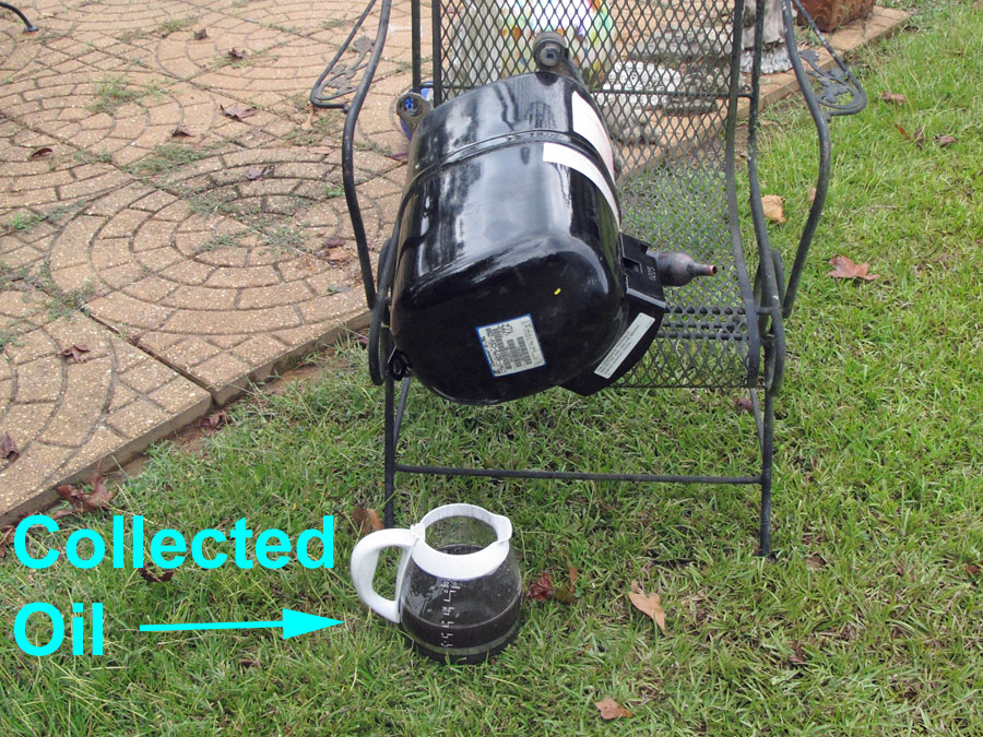
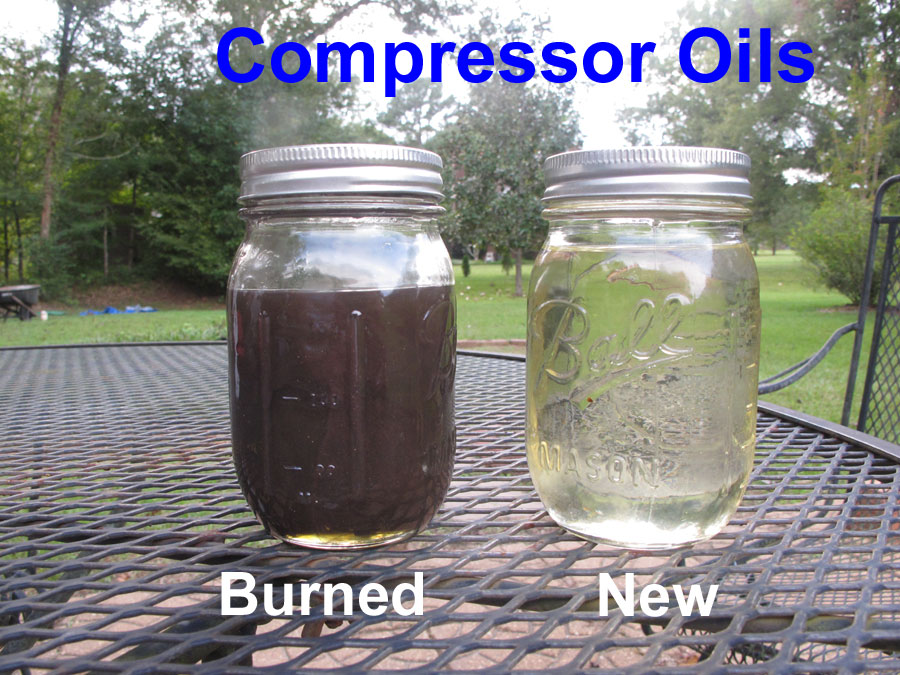
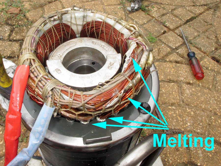
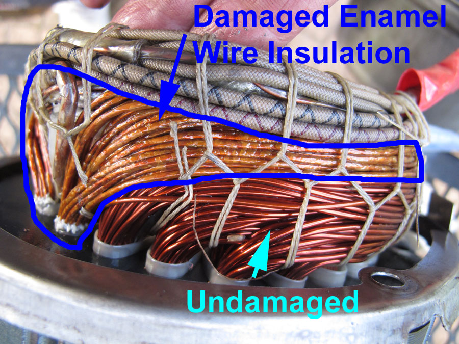
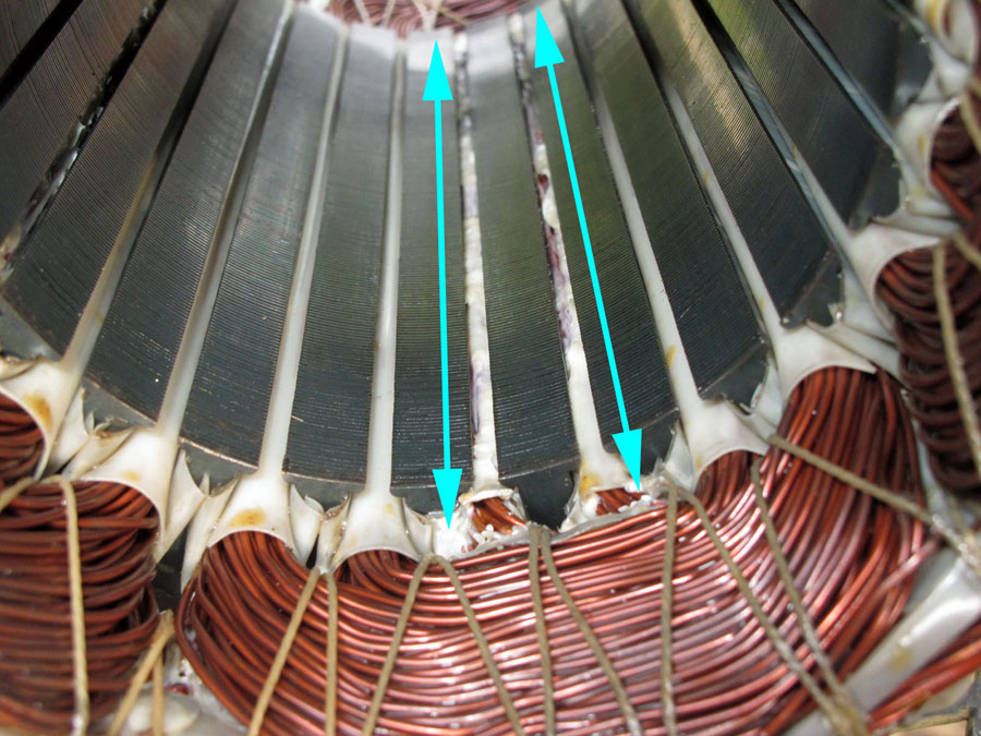
According to homeowners, this air conditioner failed when the air condition technician shorted something out which caused a voltage surge. In addition, the causing the two-speed compressor to fail, it caused the fan of a different condenser unit to fail and the auto-play box on their piano. I was hired as an expert electrical engineer by the insurance company of technician. The oil in the compressor was burned. This cannot occur in one or two seconds. To break down oil, it has to be overheated for a long period of time usually repeatedly. Ditto for the motor winding, all of one the windings is burned. This is not a localized (spot) failure. It took heat over a long period of time to blister and crack the enamel insulation. As for the other items, the circuit breaker panel box for the two- speed compressor had built in surge protection.
For Maximum Resolution, Click on the Body of the Picture.
| Winding Resistances | |||
| Winding | Ideal | Actual | |
| T1-T2 | Ext. Main | 0.80 | 0.80 |
| T1-T3 | 2-Pole Start | 3.20 | 0.50 |
| T1-T7 | Main | 1.30 | 1.40 |
| T1-T8 | 4-Pole Start | 3.10 | 3.50 |
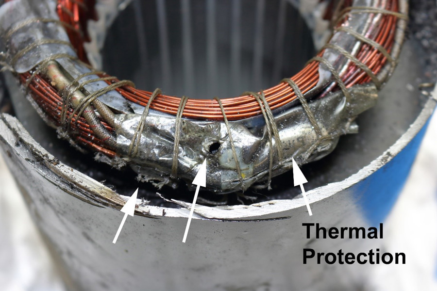
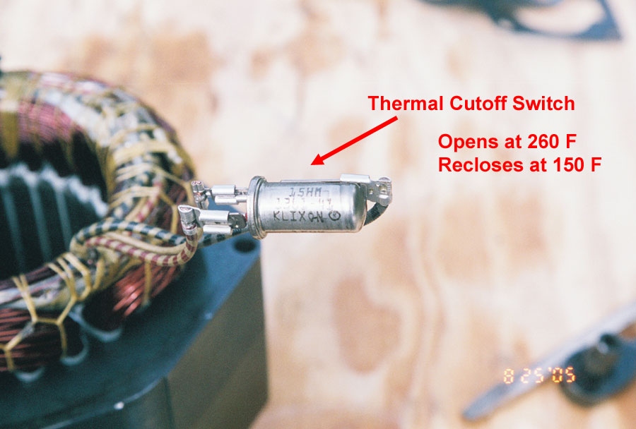
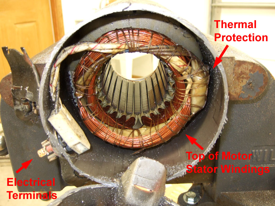
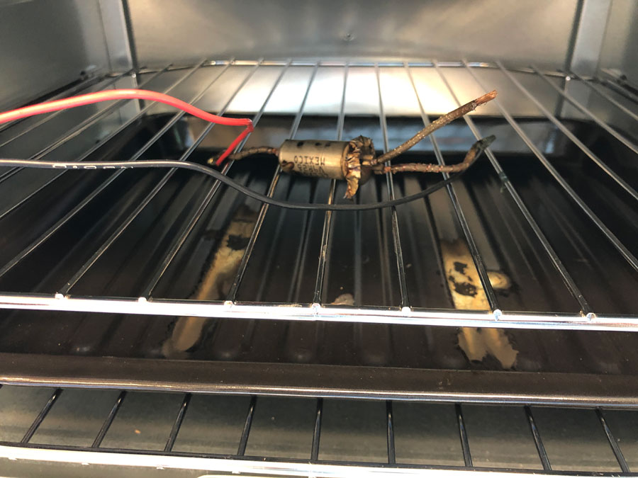
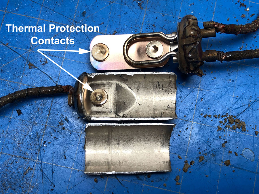
Motors on both scroll and reciprocating compressors have auto-resetting thermal protection. The thermal protector should be tested in an oven to determine if the contacts are stuck. Then the metal housing should be removed, and the contacts examined to determine if overheating occurred.
For Maximum Resolution, Click on the Body of the Picture.
© Copyright Dr. Ray Franco, PhD, PE | 2006-2020. All rights reserved.

