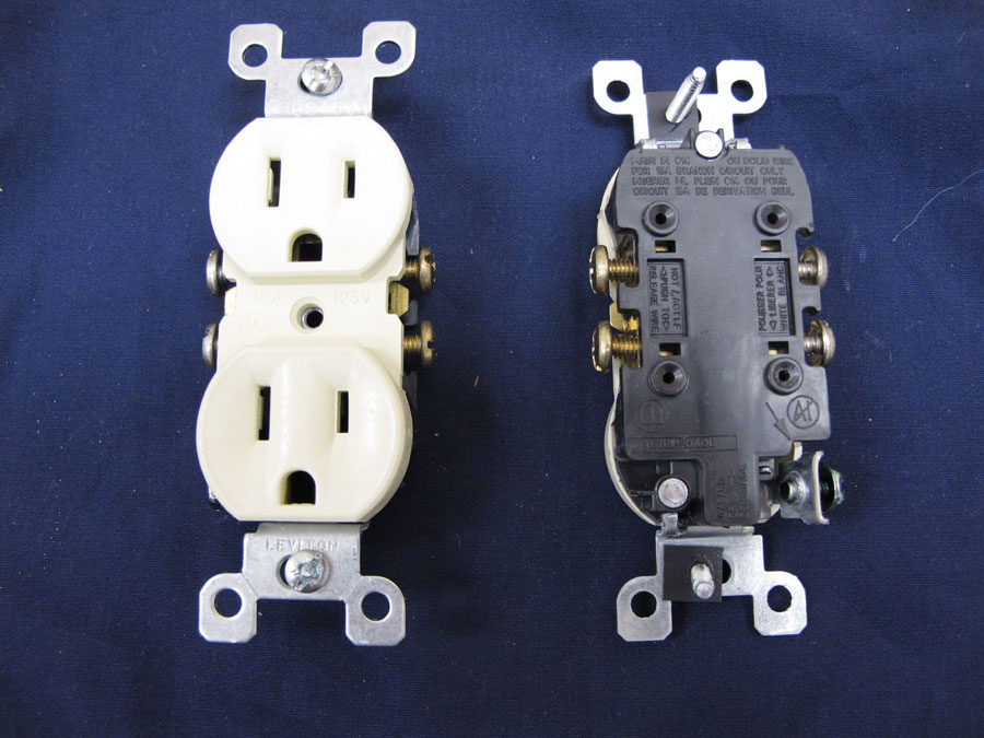
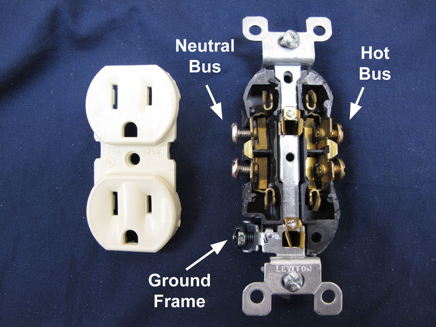
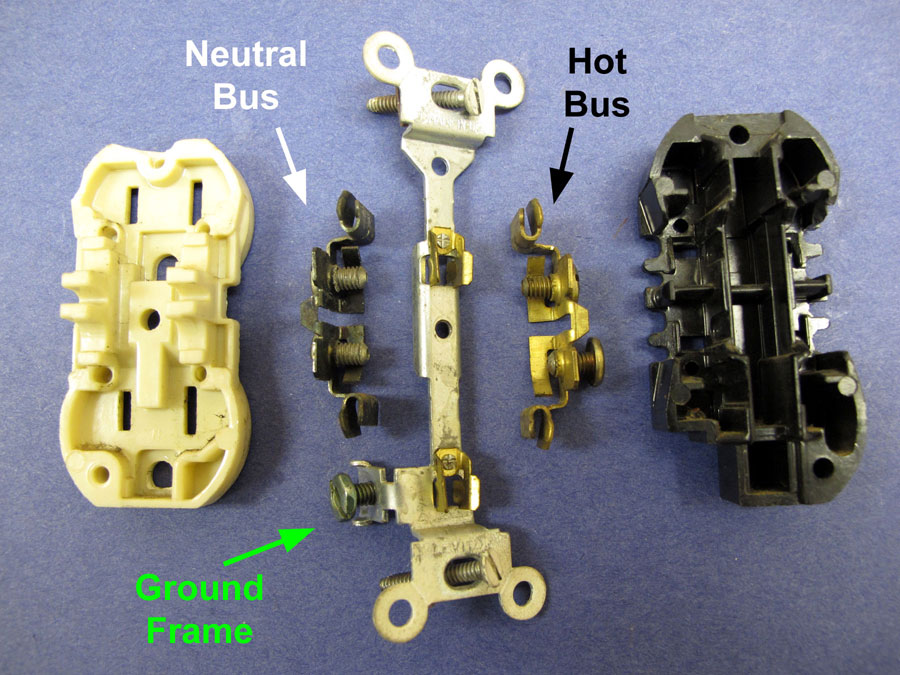
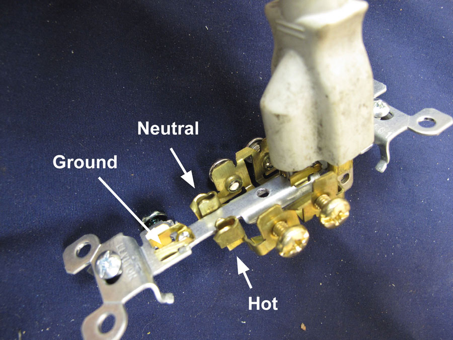
It is not necessary for a receptacle to have something plugged into it for it to cause a fire. The reason that there are two screw terminals on each bus is so that power can be supply to another receptacle or device. Hence, electrical current may be passing through the receptacle even though it has nothing plugged into it.
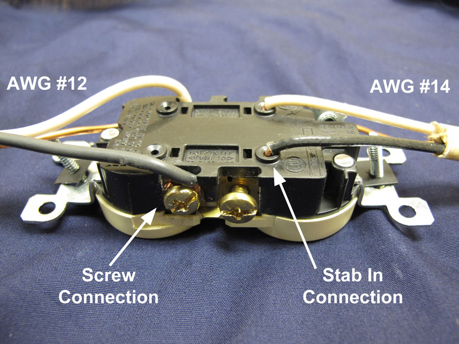
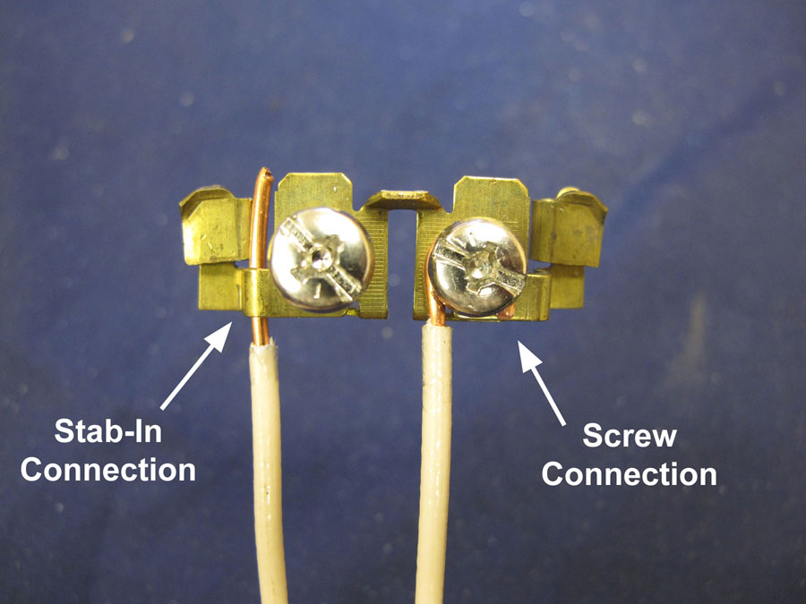
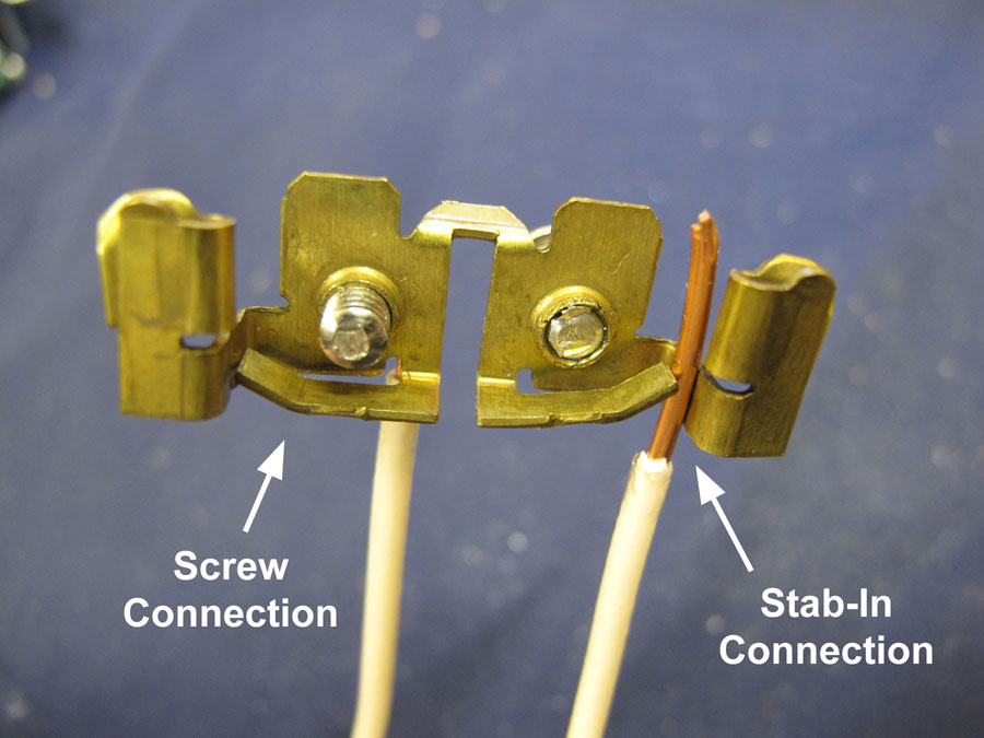
Stab-in / Push-in connections were common in the 1970's and 1980's. In 1996, UL Standard 498 was revised to only permit stab-in (push-in) connections with solid copper conductors that were size AWG #14. The manufactures reduced the size of the holes so that AWG #12 wire would not fit. AWG #12 wire is thicker and more stiff than AWG #14 wire. When the receptacle was pushed into the outlet box, too much pressure was being inserted on the spring metal gripper, and this was causing loose connections.
On duplex receptacles, there is a break tap between the screws terminals on both the "hot" and neutral buses. This allows the duplex receptacle to be spilt into two receptacles. A common use for this is to control one of the receptacles from a wall switch that turns on a table lamp.
For Maximum Resolution, Click on the Body of the Picture.
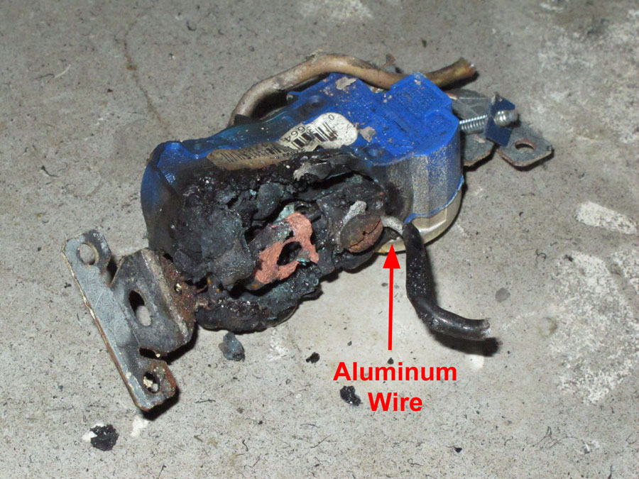
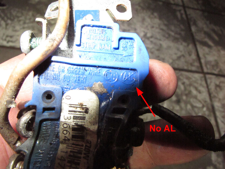
Aluminum connections are especially susceptible to loose connection due to creep.
For Maximum Resolution, Click on the Body of the Picture.
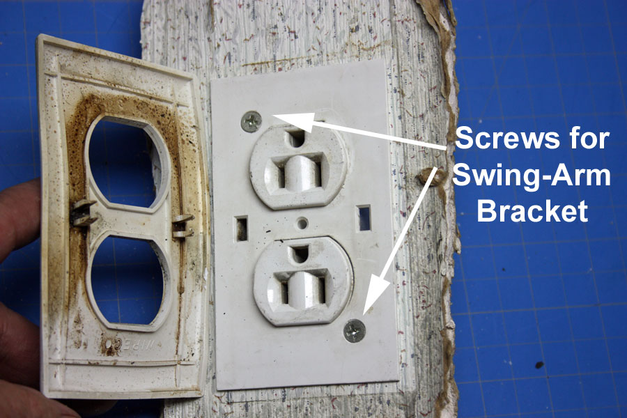
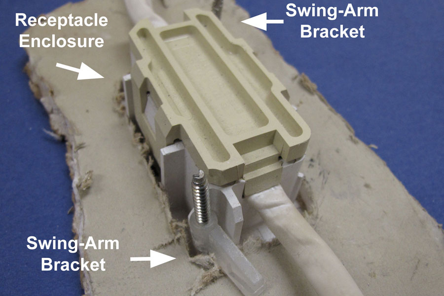
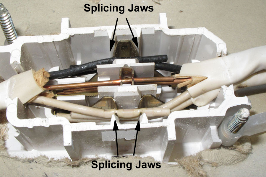
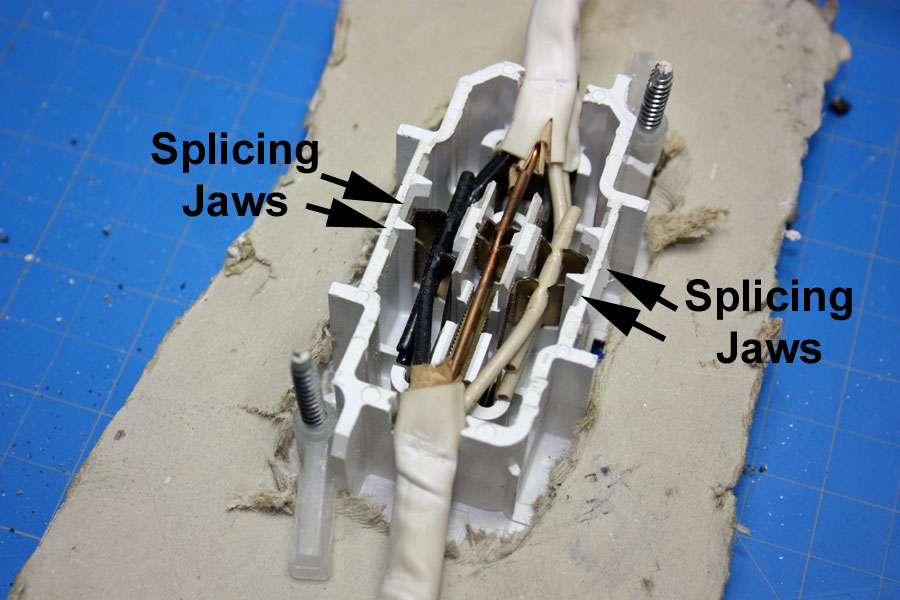
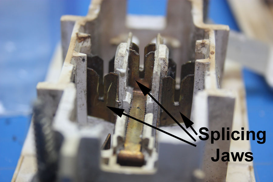
The National Electrical Code (NEC), Chapter 3, Section 300.15(E), allows for integral enclosure receptacles and light switches with brackets that secure the device to the wall. They do not require a separate junction box, nor are they mounted to a stud. The integral boxes are designed to be used only with nonmetallic (type NM) sheathed cables (Romex). Only the sheath or outer jacket must be stripped from the cable. The wire connections are made by jaws that accept multiple wires and displace (cut) the wire insulation. They are primarily used in mobile homes and manufactured buildings.
For Maximum Resolution, Click on the Body of the Picture.
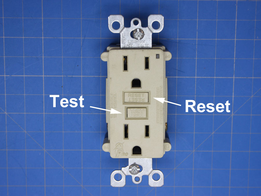
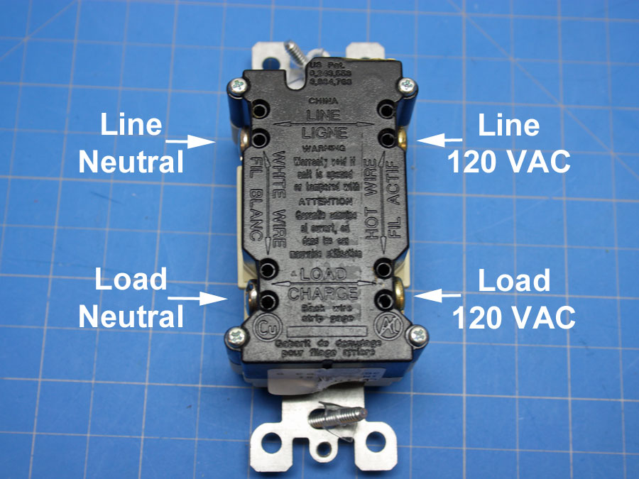
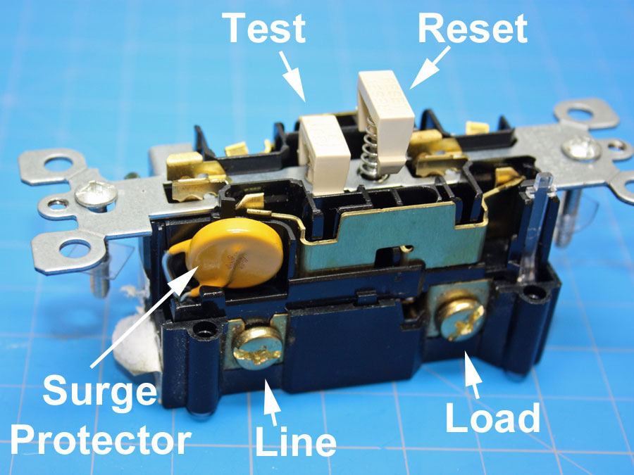
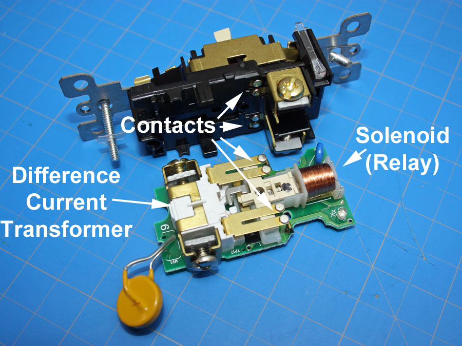
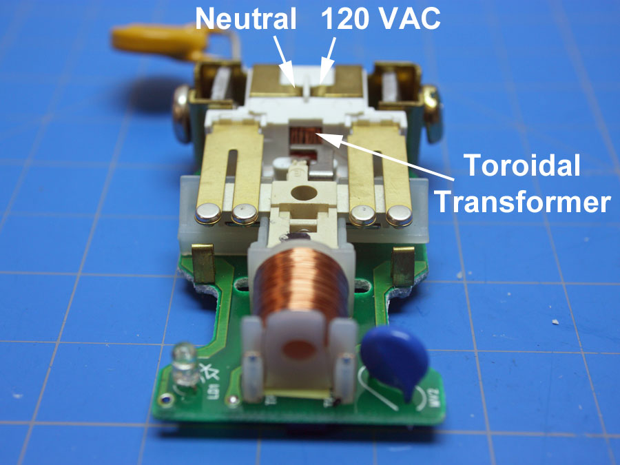
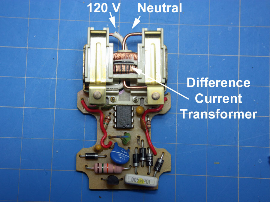
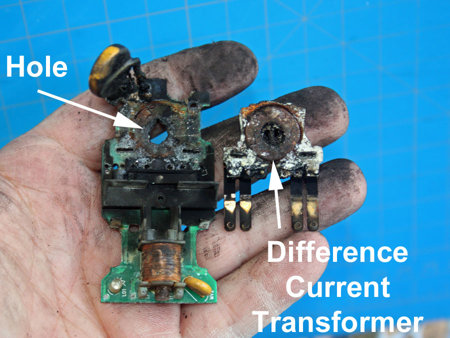
A ground-fault circuit-interrupter is a device that interrupts electricity to the load when the fault current to ground exceed a predetermined value. The fault current is the difference in the line current and the neutral current. For Class A devices, the predetermined value of the fault current is 6 mA (6/1000 amps). For fault currents between 6 mA and 264 mA, class A devices must interrupt electricity to the load according to the following equation: T = (20/I)^(1.43). When I = 6 mA, T = 5.6 sec; when I = 264 mA, T = 0.025 sec. A plot of this curve is well below the curve that causes heart fibrillation and death in heathy adults [Ref.: Leviton GFCI Brochure]. Underwriters Laboratories UL 943 is the Standard for Ground-Fault Circuit-Interrupters. GFCI were introduced in the National Electrical Code in 1968. Now they are required in all wet locations, within 6 feet of any sink, in garage/carports and outside locations.
For Maximum Resolution, Click on the Body of the Picture.
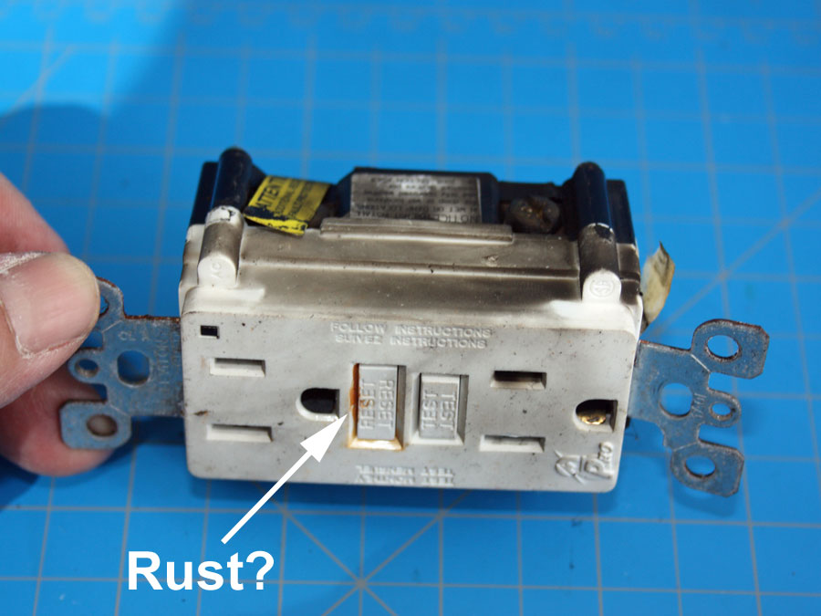
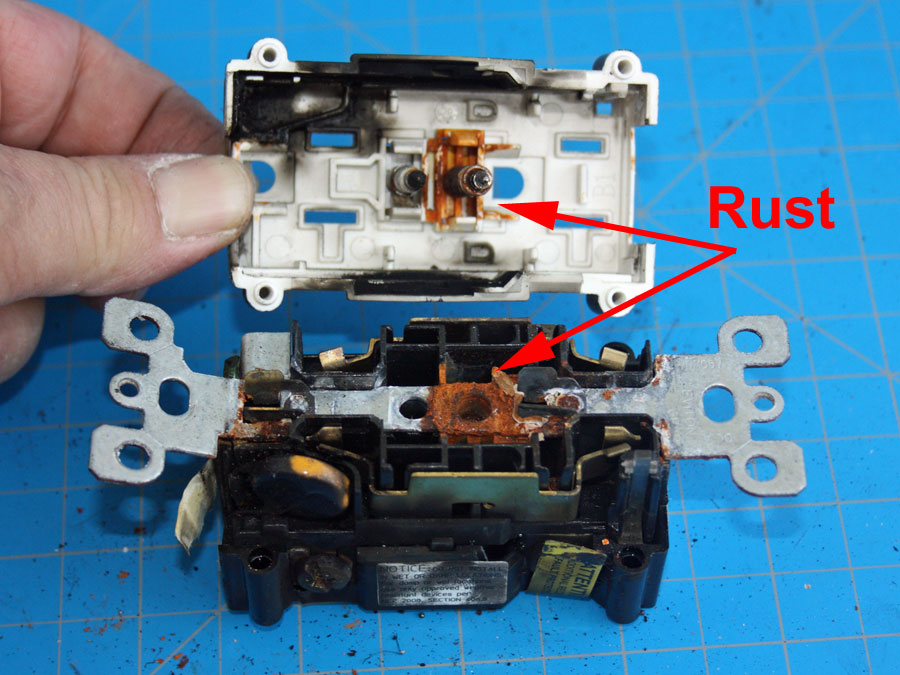
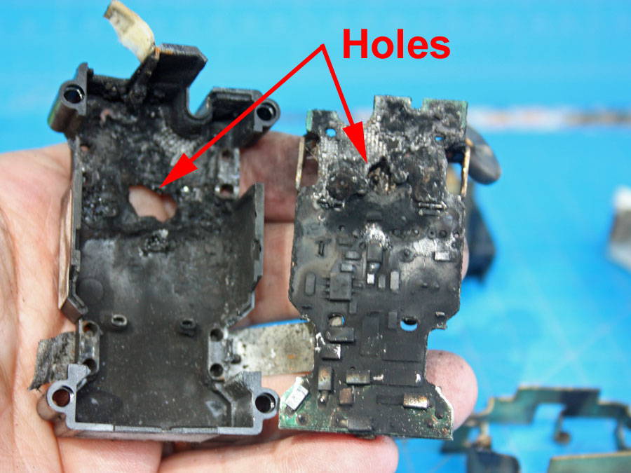
This Ground Fault Circuit Interrupter (GFCI) receptacle was given to me by Reid Sampey with Joe Gay Electric in Vicksburg, MS. It was on outside of a home without a waterproof cover. Water leaked into the receptacle.
For Maximum Resolution, Click on the Body of the Picture.

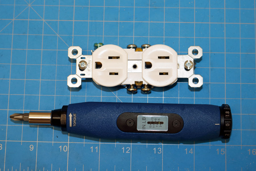
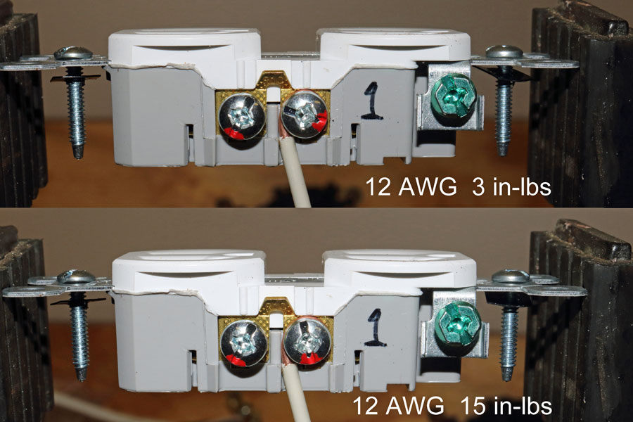
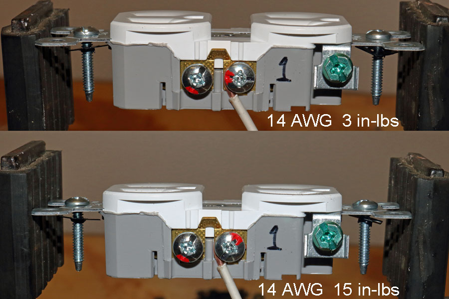
It was hypothesized that a loose screw terminal on receptacle could be determined by counting the number of threads or the measuring the position of the screw with a micrometer. To tests this hypothesis, a torque screwdriver was purchased. There was less than 1/3 of a screw turn between finger tight (3 in-lbs) and maximum torque (15 in-lbs). Hence, torque cannot be measured by counting screw threads or the screw position.
For Maximum Resolution, Click on the Body of the Picture.
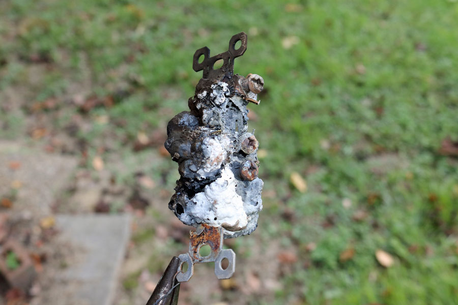
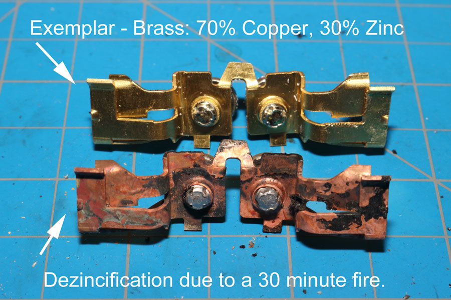
Modern receptacle are often made of thermoplastics such as polypropylene and polyvinyl chloride (PVC). The advantage of using thermoplastics is that they can be joined by ultrasonic welds. In a fire, the chloride from the PVC can combine with the water molecules in the air to form a hydrochloric gas (HCI), which is an acid. The acid can leach the Zinc out of the brass receptacle parts in 30 minutes or less.
For Maximum Resolution, Click on the Body of the Picture.

© Copyright Dr. Ray Franco, PhD, PE | 2006-2020. All rights reserved.

