Lightning is a constant current source. The average magnitude of the current, 30,000 amps (30 kA), is large, but the pulse duration, about 0.0001 seconds (100 μS), is small. The resulting voltage may be as high as 1,000,000 volts (1MV).
The thermoplastic insulation of 120/240 volt wiring will typically breakdown at around 6,000 volts (6 kV), resulting in flashover (an arc). This limits the voltage that an appliance will see to around 6,000 volts (6 kV). The short lightning pulse can cause oscillatory ringing at the natural frequency of the building wiring system. The duration of the resulting lightning transient is typically between 0.000020 to 0.000050 seconds (20 to 50 μS).
A Metal Oxide Varistor (MOV) is a voltage dependent variable resistor. It has very high resistance until the voltage exceeds a certain threshold. When the voltage exceeds the threshold voltage, Known and the Cut in VOltage, it changes to very low resistance. Thus, it limits or clamps the voltage to the cut in voltage. MOV's are composed of zinc oxide grains (90%) and other metal oxides (such as bismuth, cobalt, manganese) pressed into a ceramic like material and sandwiched between two metal plates (the electrodes). MOV's are extremely fast devices and are designed to protect sensitive electronic devices and semiconductors from switching and induced lightning surges.
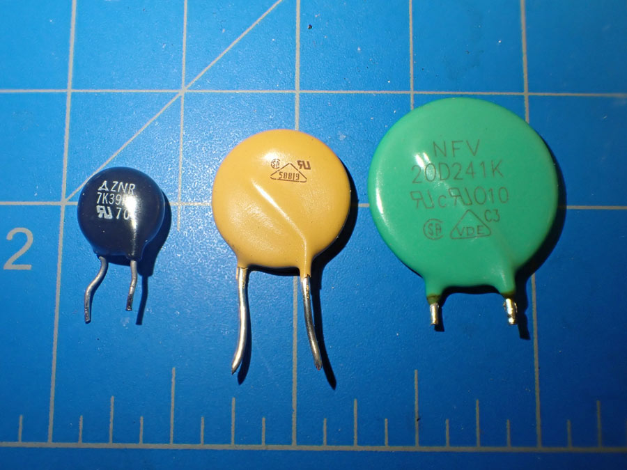
The MOV clamping voltage is controlled by the selection and ratio of the other metal oxides that are combined with the zinc oxide grains in the ceramic like matrix. Clamping voltages range between 10 and 1,000 volts. Peak current ratings range from 20 to 70,000 A, and the energy ratings range from 0.01 to 10,000 Joules (J). The current and energy rating depend on the amount of heat that the device can safely dissipate. The larger the device, the more heat it can safely dissipate.
The equation for electrical energy is: Energy = Volts x Current x Time. Hence, the amount of energy the varistor has to safely dissipate is directly proportional to the Time or pulse duration. MOV's are ideal for lightning currents that have a very short time duration typically 20 to 50 μS. A change in the overvoltage duration from 50 μS to 1 second, would increase the amount of energy that had to be safely dissipated by the MOV by a factor of 20,000. They do not make MOVs this large. MOVs are only suitable for short duration transient events.
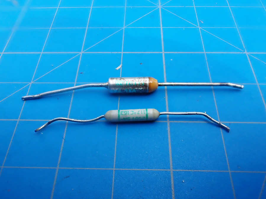
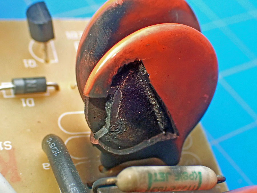
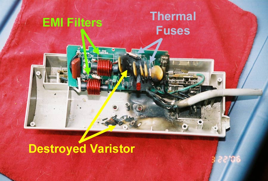
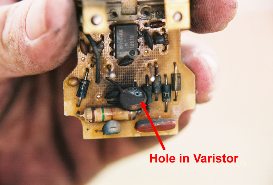
When the energy rating of an MOV is exceeded, the results can be catastrophic. MOVs can breakdown and holes can be blown in them. MOVs can catch fire! MOV fire in surge protector fires became such a problem that in February 1998, the second edition of UL 1449, Standard for Surge Protection Devices, required that surge suppressors fail in a safe manner without causing a fire. All of the surge protector that I have examined that were manufactured after 1998 have contained some type of thermal fuse. The thermal fuse is usually pressed up against a MOV or between two MOVs and held in place by mylar tape or UL-94 VW-1 flame rated shrink tubing. In addition on some of their models, Belkin and Power Sentry place fiberglass covers over the MOV's.
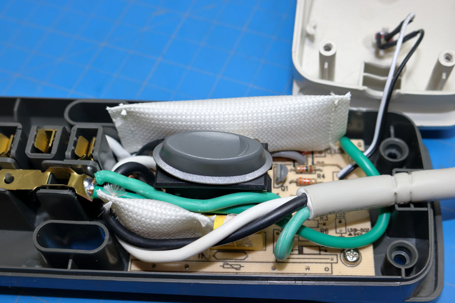
Power Strips with Surge Protection have at least one varistor between the hot (120 volts - black conductor) and neutral conductor (grounded - white conductor).
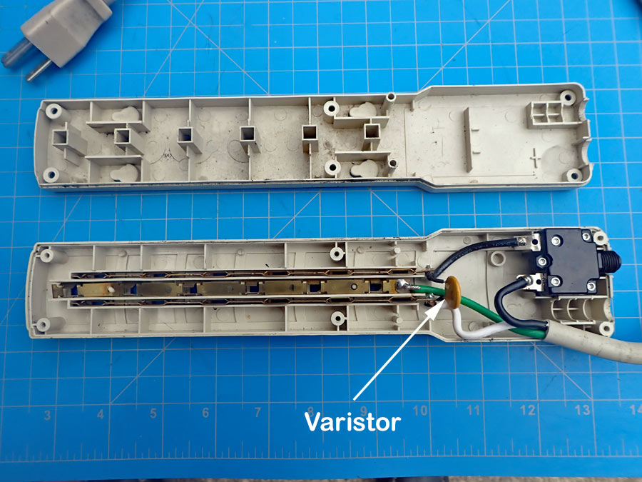
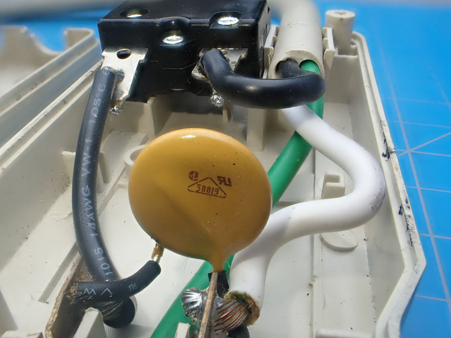
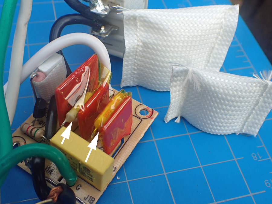
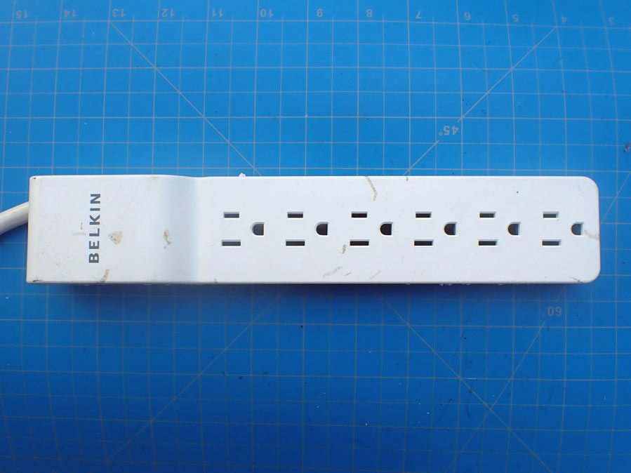
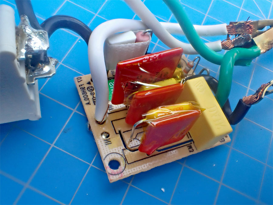
Since lightning may come in through the ground, good power strips usually also have varistors between the grounding conductor (green conductor) and the hot conductor and between the grounding conductor and neutral conductor. The Belkin power strip below has three MOVs. With the exception of the fiberglass covers over the MOV's, it is a typical power strip.
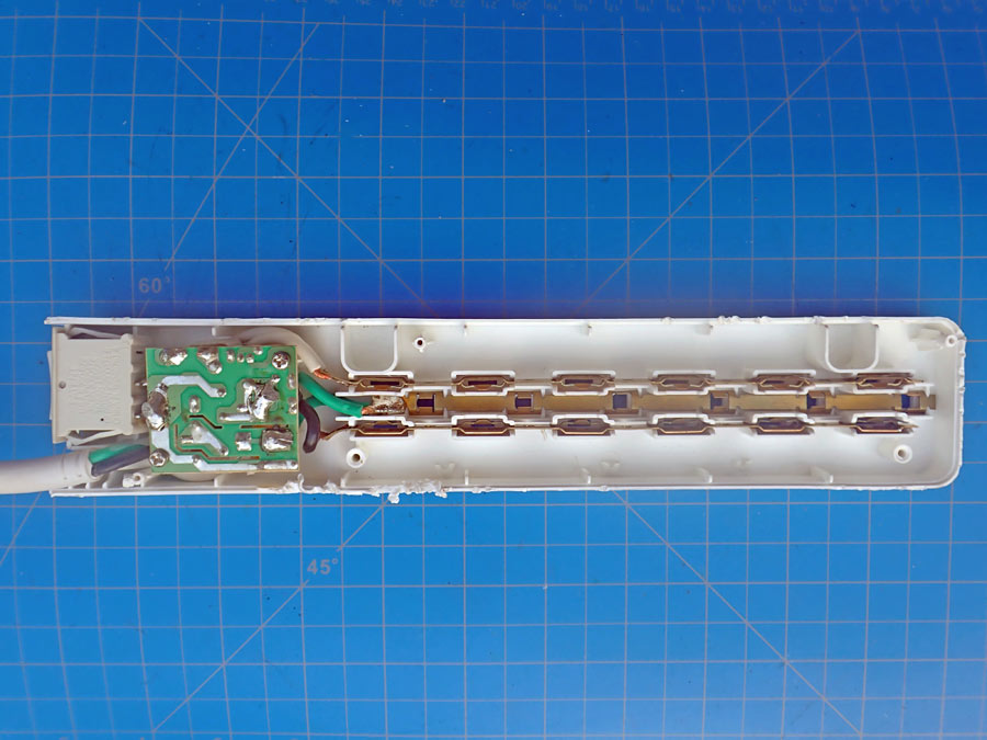

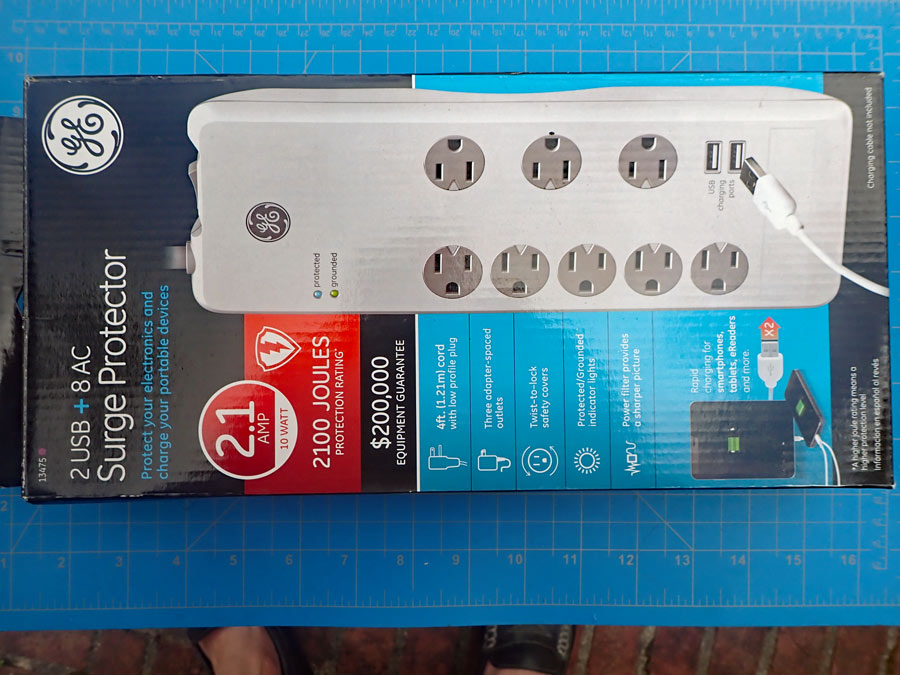
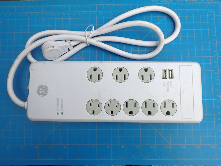
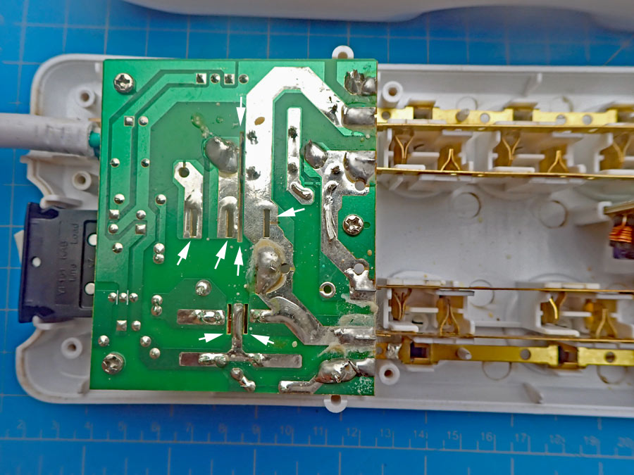
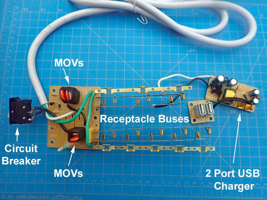
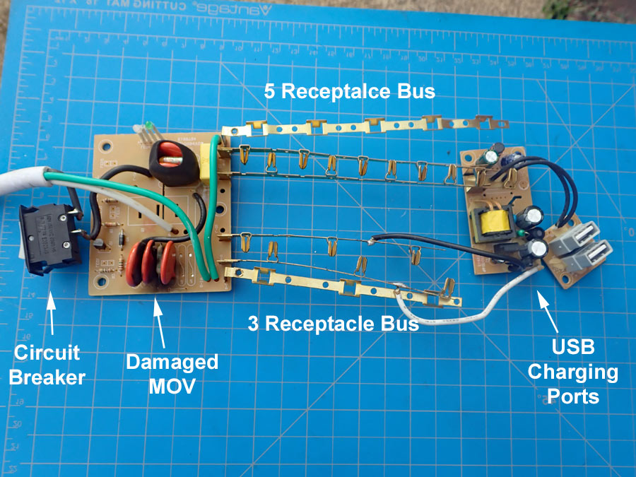
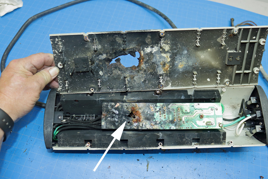
The GE power strip depicted below was purchased as an exemplar in a fire case where someone died. The power strip had two rows of receptacles. There were 5 receptacles on one row, and 3 receptacles on the other row. The power strip also contained two USB charging ports. The energy rating of the power strip was 2,100 Joules (watt-seconds). This power strip also has indicator LEDs to inform the user that the power strip is properly grounded and that the surge protection is working.
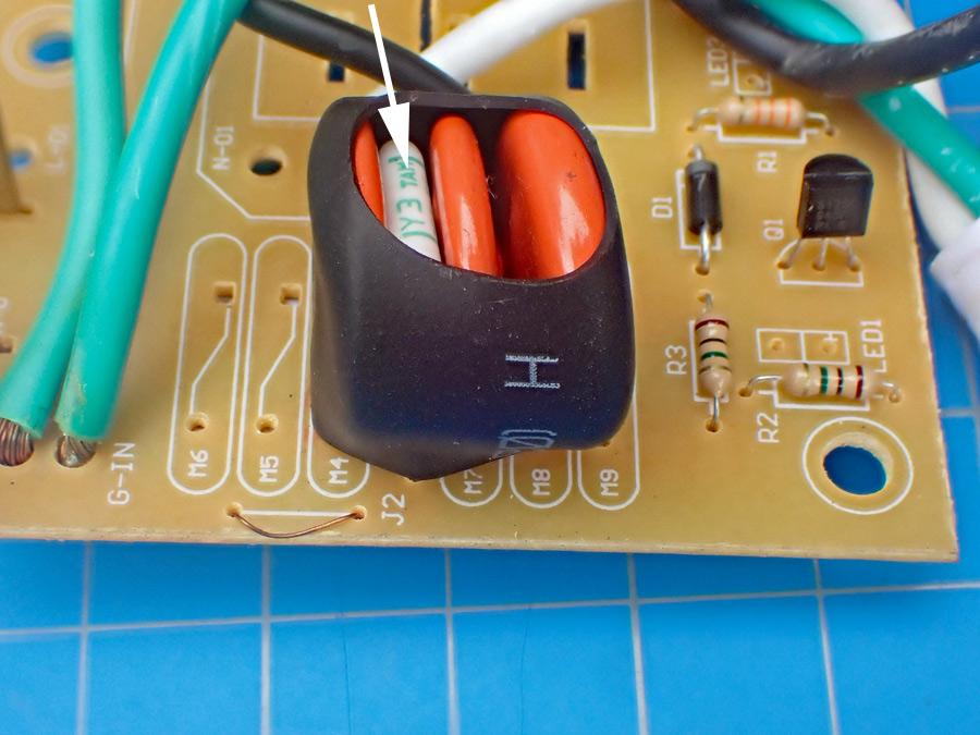
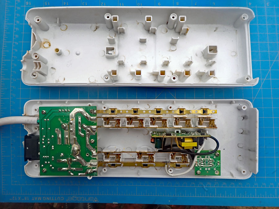
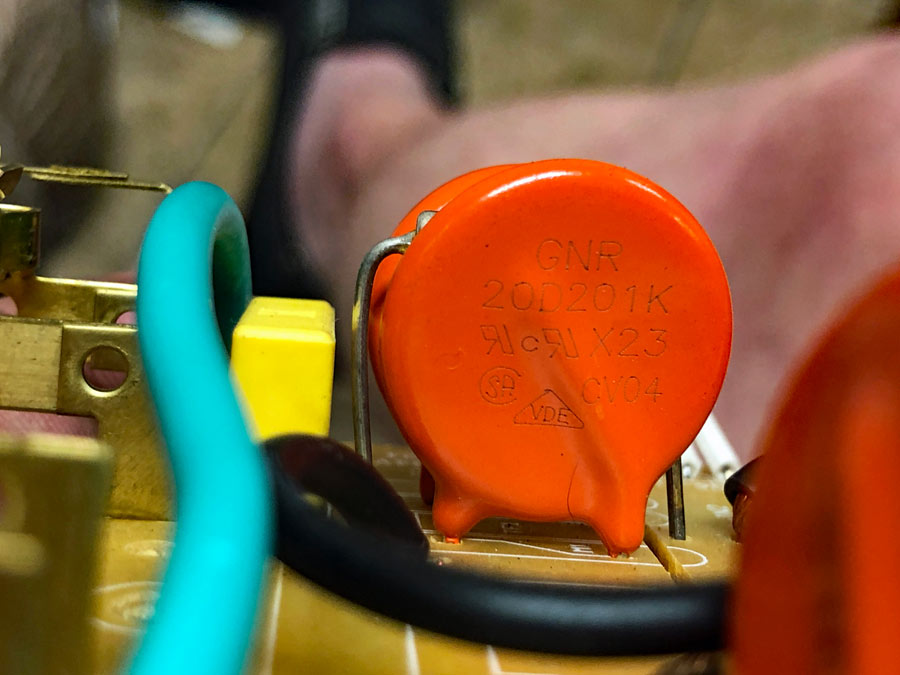
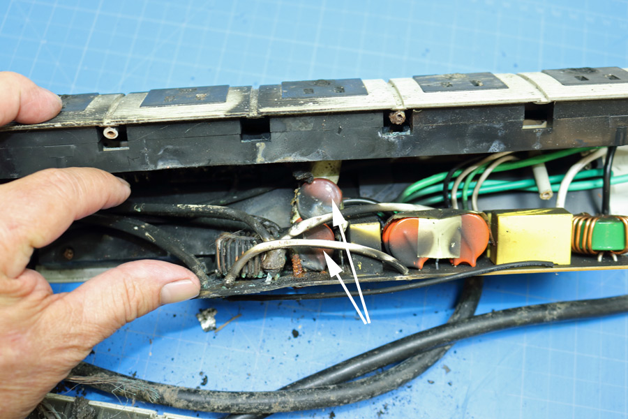
There were 5 identical MOV's (Part No. 20D201K) on the printed circuit board. They were in two groups: One group with 3 MOVs and another group with 2 MOVs. Each group contained a thermal fuse. Each group was wrapped in thick black shrink tubing. The shrink tubing (UL File No.: E203950) had a UL-94 VW-1 flammability rating.
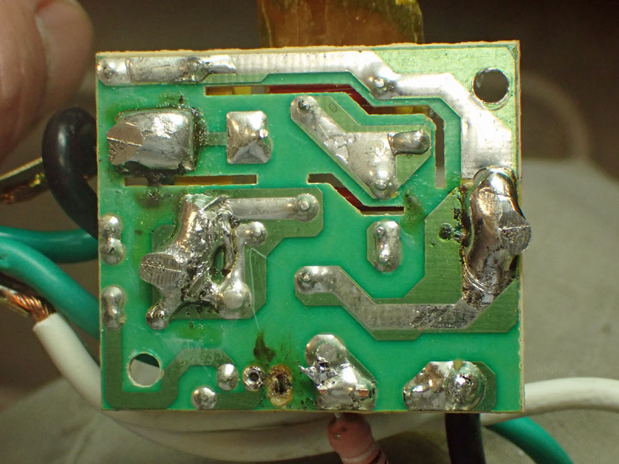
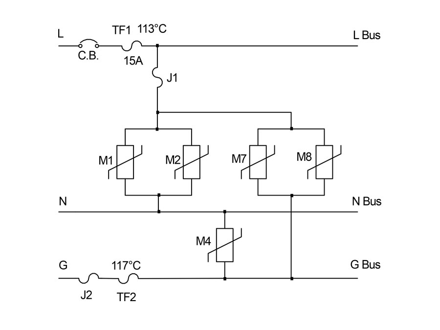
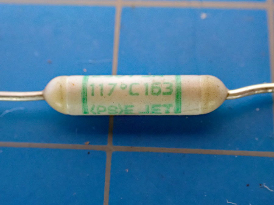
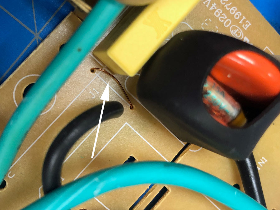
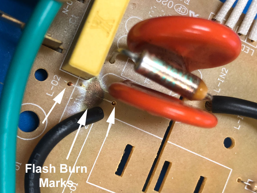
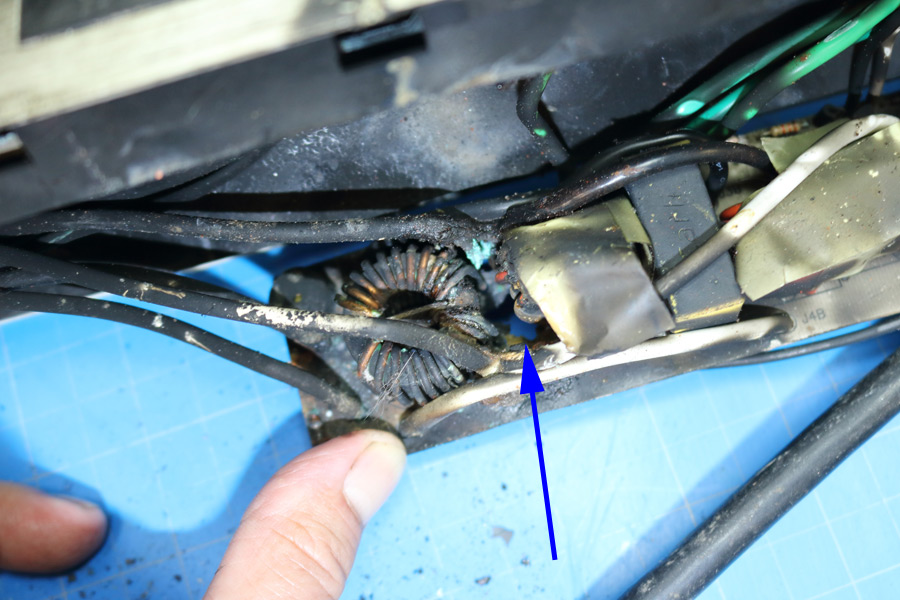
In the laboratory, 240-volts AC was intentionally connected to the power strip. It failed instantaneously. There was a loud pop and a little bit of smoke. There was a catastrophic failure of one of the MOV's. The thermal fuse, rated at 117°C (243°F), that was adjacent to the destroyed varistor did not activate, nor did the 240-volt, 30-amp, circuit breaker trip. On examining deeper why the thermal fuse did not melt, it was observed that there were two single strand wire fuse jumpers on the printed circuit board, and both of these blew. This shut off all power to the power strip.
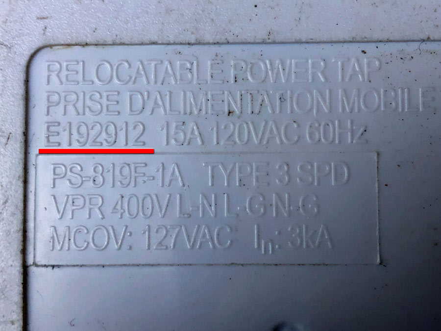
The surge protector is guaranteed for $200,000 to protect equipment connected to it. According to instructions and warranty that came with the surge protector, (Instructions and Warranty), Jasco Products Company in Oklahoma City, OK, sells and distributes the surge protector and is responsible for its warranty. Jasco Product Company licenses the GE trademark. The instructions, packaging, and stamped into the plastic body is "made in China". The UL file number, stamped into the plastic body was traced to KAB Enterprise Co. LTD. in Taiwan (UL File No. E192912).
The power strip that was in the fire was heat damaged. It was x-rayed. However, it was difficult to determine from the x-rays if any of the MOVs failed.
The power strip depicted below was sent to me by a fire investigator for laboratory examination. He suspected that it was the cause of the fire. I produced a written report, and the case settled without having to go to court.
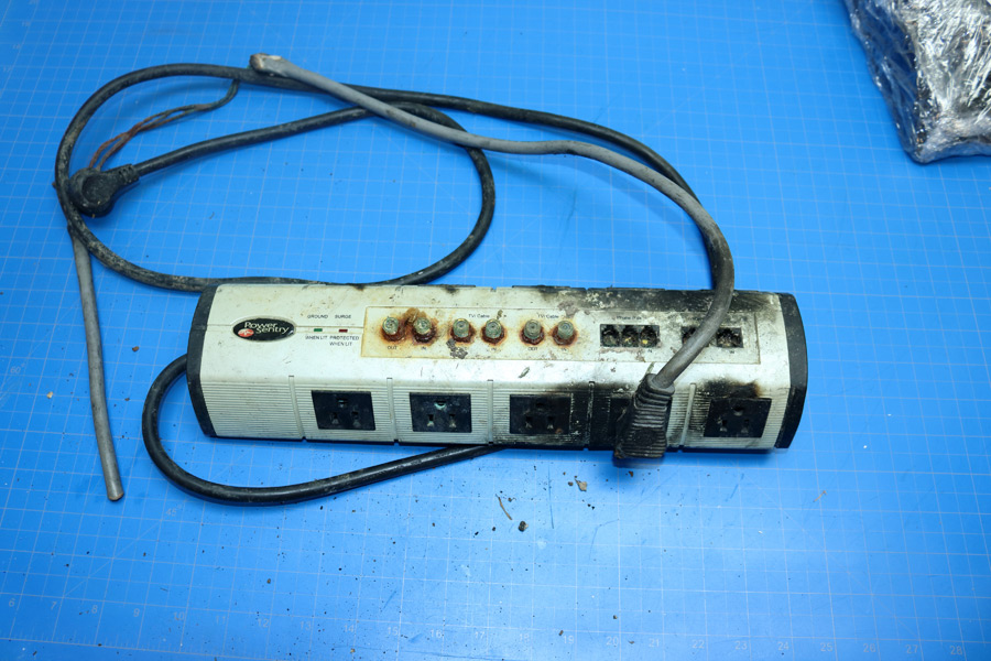
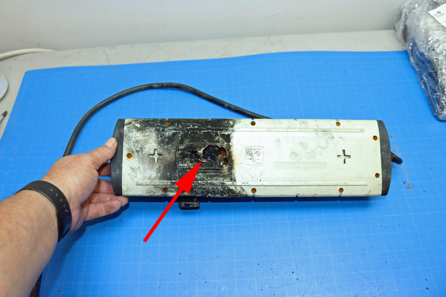
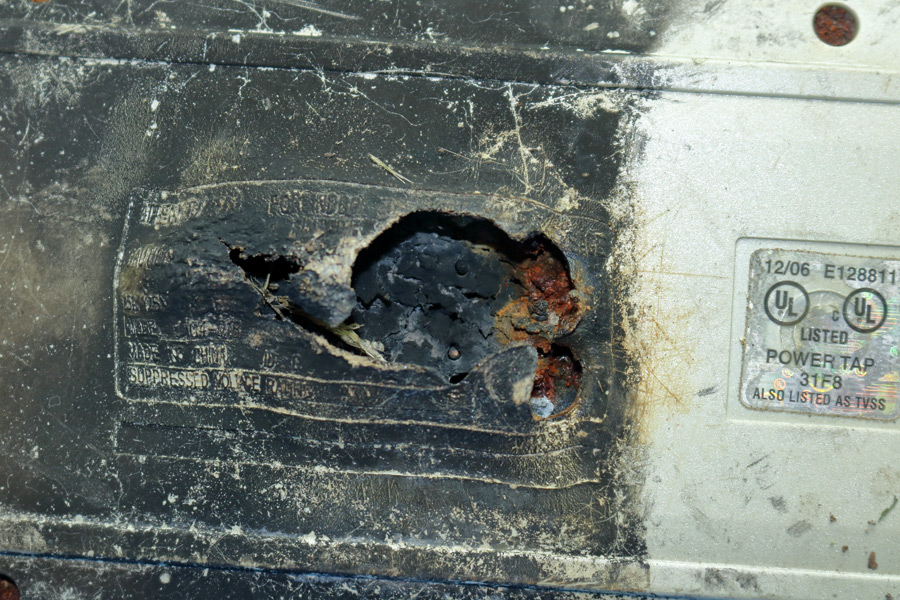

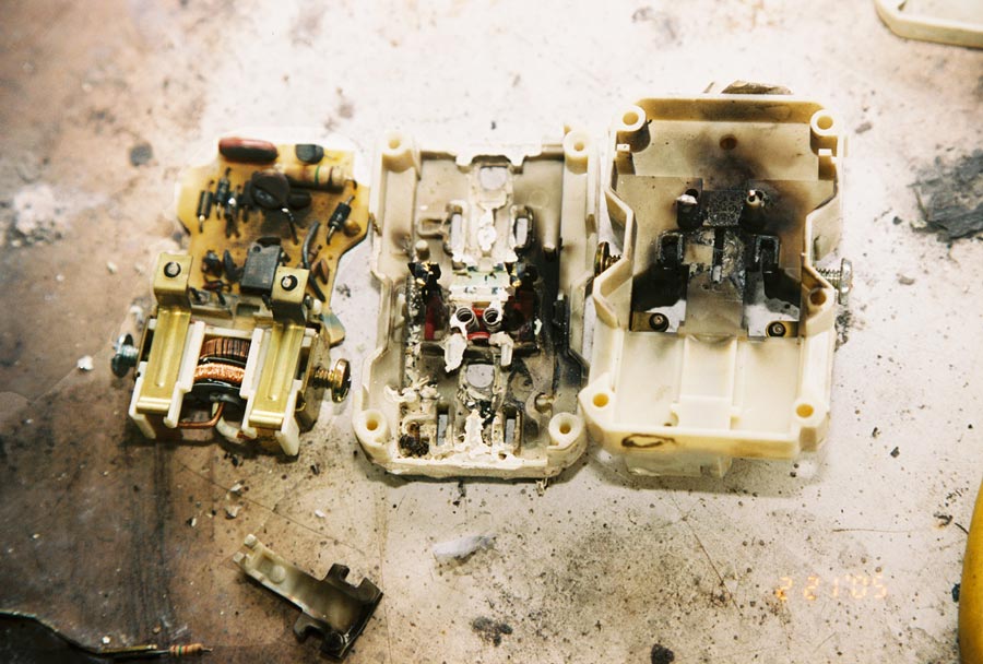
The two damaged surge protectors below were caused by an open neutral. An open neutral is not a surge; it is a long-time event. Surge protectors will be damaged by an open neutral, but they should fail in a safe manner and not cause a fire.
The requirement for GFCI has been in the NEC since 1975.
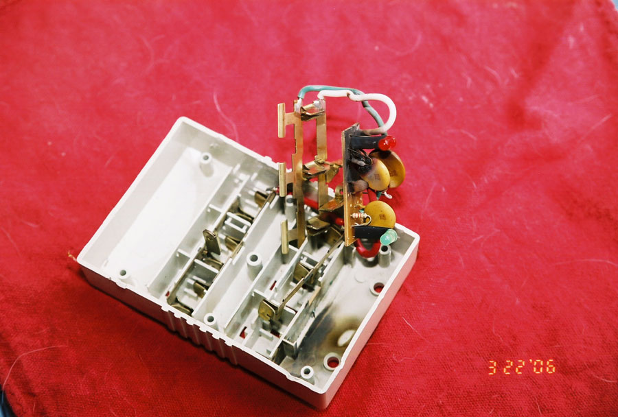
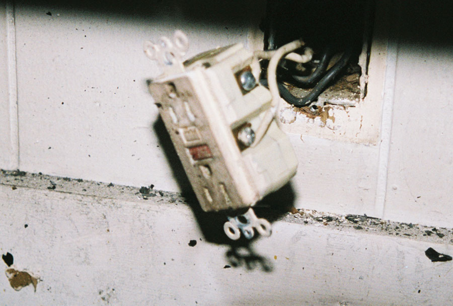
Case History: While replacing a distribution transformer, the high voltage line came in contact with the secondary of the transformer. There were nine homes connected to this transformer. All of the homes suffered some damage. At the one of the homes, the refrigerator condenser fan caught on fire. The internal damage to the surge suppression device in the Ground Fault Circuit Interrupter (GFCI) receptacle was a result of it being overloaded. More precisely, the varistor attempted to suppress the voltage surge, but the fault contained more electrical energy than the varistor could safely dissipate.
For Maximum Resolution, Click on the Body of the Picture.
© Copyright Dr. Ray Franco, PhD, PE | 2006-2020. All rights reserved.

